The next PeeCeeBee
Hello people!
A new amplifier has been cooking for some months and a few days ago was finalized. By design it is a detour from our beloved "PeeCeeBee" design. A perfboard version is playing music and tones right now and all I can say is that electrically and sonically it is the step forward for the simple design that has been rocking for the last four years.
The new design is "marginally" complex, uses basic LED biased active CCS, all small signal transistors the easy to access BC556B/546B, emitter-follower VAS with current limit and diode-clamped soft-ish clipping with much less HF distortion than usual, uses input inclusive compensation in addition to usual Miller compensation, produces ~100V/us slew rate, lower overall THD, MUCH less low frequency distortion and MUCH higher damping factor at LF.
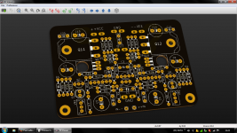
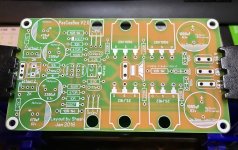
I have ordered a couple prototypes of the initial layout. The board would look kind of like the picture (with what Kicad calls "black" mask 😀 ). The PCB is 2 layer PTH. The full test results, schematic and layout will be uploaded in the new thread.
Hello people!
A new amplifier has been cooking for some months and a few days ago was finalized. By design it is a detour from our beloved "PeeCeeBee" design. A perfboard version is playing music and tones right now and all I can say is that electrically and sonically it is the step forward for the simple design that has been rocking for the last four years.
The new design is "marginally" complex, uses basic LED biased active CCS, all small signal transistors the easy to access BC556B/546B, emitter-follower VAS with current limit and diode-clamped soft-ish clipping with much less HF distortion than usual, uses input inclusive compensation in addition to usual Miller compensation, produces ~100V/us slew rate, lower overall THD, MUCH less low frequency distortion and MUCH higher damping factor at LF.
I have ordered a couple prototypes of the initial layout. The board would look kind of like the picture (with what Kicad calls "black" mask 😀 ). The PCB is 2 layer PTH. The full test results, schematic and layout will be uploaded in the new thread.
Attachments
Great going [emoji106] [emoji106] [emoji106]Hello people!
A new amplifier has been cooking for some months and a few days ago was finalized. By design it is a detour from our beloved "PeeCeeBee" design. A perfboard version is playing music and tones right now and all I can say is that electrically and sonically it is the step forward for the simple design that has been rocking for the last four years.
The new design is "marginally" complex, uses basic LED biased active CCS, all small signal transistors the easy to access BC556B/546B, emitter-follower VAS with current limit and diode-clamped soft-ish clipping with much less HF distortion than usual, uses input inclusive compensation in addition to usual Miller compensation, produces ~100V/us slew rate, lower overall THD, MUCH less low frequency distortion and MUCH higher damping factor at LF.
I have ordered a couple prototypes of the initial layout. The board would look kind of like the picture (with what Kicad calls "black" mask 😀 ). The PCB is 2 layer PTH. The full test results, schematic and layout will be uploaded in the new thread.
Sent from my GT-N7100 using Tapatalk
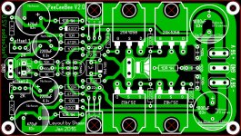
I will use Nichicon UFG series Audio Grade Electrolytic Capacitors
Nichicon UFG series capacitors diameter is bigger than other capacitors.
Hello btesize,
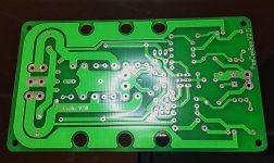
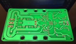
I think there is a wrong lead spacing on your PCB
UFG 470µF/63V ---> 7.5 mm (like 1000µF/63V)
Hello btesize,
I think there is a wrong lead spacing on your PCB
UFG 470µF/63V ---> 7.5 mm (like 1000µF/63V)
Hi CB89
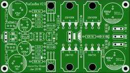
thanks for correction.🙂
file updated
Attachments
By design it is a detour from our beloved "PeeCeeBee" design. A perfboard version is playing music and tones right now and all I can say is that electrically and sonically it is the step forward for the simple design that has been rocking for the last four years.

Things that remain the same as the other PeeCeeBees are the feedback network, lateral mosfets, no driver stage, no output inductor, no magics and no secrets. 😀 🙄
The difference is that this time the boards will be available for purchase internationally, with full schematic and BOM .
.
The thread will be a DIY build thread (with rules), again! 🙄
The difference is that this time the boards will be available for purchase internationally, with full schematic and BOM
.The thread will be a DIY build thread (with rules), again! 🙄
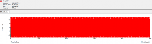
Here is a THD simulation of ~10W into 8R load with 70mA FET current. Traced up to 500mS with 500nS steps.
VeryGoood Shaan thd: 0,0019

Shaan, from where do you get your supply of Lateral Mosfets? Thanks.
Kolkata chandni market. Shop - Railton. 🙂
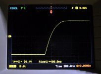
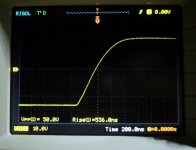
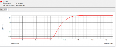
Here is a positive slew simulation and a couple real-world test with 100KHz 2.4V 16nS square input and no load connected.
PS=+/-35V, Cdom=50pF, VAS bias=11mA, Input bias=1.5mA, MOSFET bias=30mA, Input filter=1K+100pF.
Pic 1 - Simulation trace with input filter installed.
Pic 2 - Real-world trace with input filter installed.
Pic 3 - Real-world trace with no input filter.
Pic 4 - The humble amp with the 74HC14 signal source.
Guess we are in the safe zone, eh?
Attachments

- Home
- Amplifiers
- Solid State
- PeeCeeBee