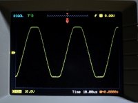
Zoom further in and check top and bottom edges for oscillations during recovery from overload.
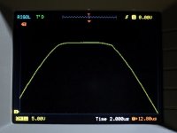
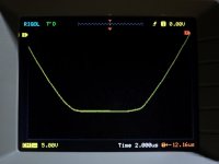
Here is how the two edges look up close. I hope this clears it.
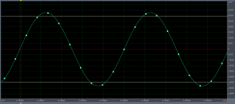
However, I think I found the cause behind the "anomalous" looking recovery slopes of top/bottom edges at low zoom levels (See attachment 4). The maximum levels of the 16bit/192KHz signal from the PC is quite stable, but not That stable due to (still) less than enough number of bits present near or at top/bottom of the wave for the interpolation to keep the maximum level constant. This results into very small level inconsistency near the top/bottom and makes the clipped waveform a little jittery both at start and end of clipped edges due to non-constant time of clipping. Still, this does not invalidate the test results as it did not induce any oscillation in the amplifier.
🙂
Pic 1 - The full clipped signal
Pic 2 - Top edge
Pic 3 - Bottom edge
Pic 4 - Snapshot of the 20KHz tone from audio editor
Attachments
Last edited:
The maximum levels of the 16bit/192KHz signal from the PC is quite stable, but not That stable due to (still) less than enough number of bits present near or at top/bottom of the wave for the interpolation to keep the maximum level constant.
Interestingly,
The inconsistent level problem goes away with the KHz frequency having a number which is integer multiple or fraction of the bit depth number. The max-level of a 4KHz, 8KHz, 16KHz or 32KHz looks totally constant (it may also have something to do with the sampling frequency, not sure
 ). I think I am missing a lot in this area as I don't know a lot about sampling/synthesis, but maybe I will do future HF tests with these frequencies instead.
Edit: 😱 A little more experimenting in the editor tells me that it really has more to do with the sampling frequency. The top/bottom levels are constant as long as the sampling frequency is an integer multiple of the tone frequency.
Last edited:
hey shaan,
from where do you buy 2SK1058 and 2SJ162. i would love to build your peeceebee v2 ..
regards
sekhar
from where do you buy 2SK1058 and 2SJ162. i would love to build your peeceebee v2 ..
regards
sekhar
Hello Sekhar.
I buy them from Railton Electronics in Kolkata chandni market.
🙂
ok thanks for the info ..hmmm finding it in mumbai will be difficult i guess..may be next time i visit my home town (siliguri) i will stop over at kolkata to buy the fets.
You're welcome.
I thought these FETs come here via Mumbai.
May be ... How much do you buy these fets for ??
May be ... How much do you buy these fets for ??
Rupees 250 to 300 each.
I have been talking to Mr. Vineet from Railton, Kolkata. He does not have stock or prices.
Alternative places are New Gemini elec., Nahar elec., Naresh radio., Indian elec., Cheap radio. etc. I almost always get them in Railton but ya, occasionally they do run out of stocks.
Here is a couple links to Hifivision.com posts where a couple local friends wrote what they think about V3's performance. They are the guys whose places I attended in the last weeks.
Tracing The PeeCeeBee - Post 88
Tracing The PeeCeeBee - Post 84
🙂
Tracing The PeeCeeBee - Post 88
Tracing The PeeCeeBee - Post 84
🙂
...and the secret is so called "pseudo-cascoded" VAS's? These behave exactly the same. Fast, stable, Softish-clipping (this technique is and was used in electric instrumental amplification, when too much signal level and "occasional clipping" are quite frequent).Hi Gm.
Thnaks.
Yes V4 has rounded clip edges (soft-ish clipping).
There was oscillation with zobel removed, oscillation with input RF shunt removed, VAS current instability, asymmetrical clipping, high noise, less than 30V/uS slew rate unacceptably high LF distortion and loose bass. But this is V4's story from 2016, when it was lying on bed being assembled, tortured, overloaded, dissected and reassembled over and over.
Eventually it found the way it sings best with the least effort.
Now we have no oscillation when both zobel and input RF shunt removed, rock-solid VAS bias, symmetrical clipping, ultra low noise, 100V/uS slew rate, ultra low LF distortion and bass as tight as we can imagine (You will be surprised how good a basic LatFet amp's bass can be!). V4 retains the superb tonal quality of the previous PeeCeeBee versions and delivers the ever so sparkling highs with grace.

p.s. Very nice results (now I have looked at the "zoomed" ones)!!!
...and the secret is so called "pseudo-cascoded" VAS's? These behave exactly the same. Fast, stable, Softish-clipping (this technique is and was used in electric instrumental amplification, when too much signal level and "occasional clipping" are quite frequent).
p.s. Very nice results (now I have looked at the "zoomed" ones)!!!
Hi GM!
No need to make assumptions. I know it has been done before. I do not claim to have developed something new; only yet another way we can have fun building amplifiers. All "secrets" will be revealed as soon as I get the first prototype PCBs. Bear with me, please.
V4 is not using a cascoded VAS. I don't like sacrificing a couple volts in an amplifier that uses Lateral MOSFETs and has to run from only +/-35VDC alone. Like with any other amplifier, it will be good to not let the amp go into clipping. But if so happens, the artifacts will sound less "harsh" to the ear.
Thanks for the kind words. That's how far I could zoom with my scope. When I get a more expensive one, I will upload 16K JPEGs and crash the diyA servers. 😛 🙂
PeeCeeBee 1.0 finily singing
Hi Shaan and Fellas.
After any month having the 1.0 boards from Olaf i could finish the little Beasts
last days.🙂.
I like the simple, rock stable circuit- really very well design.
Only little problem i have is: one channel works with bias 160mA- could be set via 1k trimmer to 169mA and second is max. to minimize to 190mA.
Offset goes crossing zero point.
For my knowledge i don't understand that differences?
Has it to do with different Vf-S (gm) or better measuring the diodes for bias?
Wish part are to change to have two channels on same level?
But all that don't hints me to hang it on speaker and let it play music. 🙂 😀.
After hours and days now is left over: WOW and AHA moments.
Another little Animal in my collection, what i like for most how it
works.
It is all there how i like to listen- dynamic, crystal clear with brilliance in top
end- on other end real good roling low end.
Also good image in low level listening.
My only little thought is: had i better choose resistors what give warmer/darker tonality, like prp types?
Attachments
Woah! 

What a cute little PeeCeeBee pair there Bangla!!!!! Glad to know you're happy with them. Thanks to Olaf again for sharing the layout.
You can safely ignore the 30mA difference in bias of the two channels. It won't cause any sonic difference between the two channels. If you're using a single heatsink for two channels then the slight difference in idle dissipation of the two channels won't be noticeable.
Matched input and VAS pairs will definitely bring both audible and operational advantages.
I don't think "special" resistors would do any trick in this amplifier other than making it look better, though. 😉
Happy listening and Happy DIYing.
shaan
Thanks Shaan for kind words and advise.
It would be interesting for me to know where i can screw to came to closer bias.
In other boards i could see 2,2k trimmer- so more variable?
Audible it is a real nice sounding Amp without ccs- thanks for sharing, that we can enjoy it.
It would be interesting for me to know where i can screw to came to closer bias.
In other boards i could see 2,2k trimmer- so more variable?
Audible it is a real nice sounding Amp without ccs- thanks for sharing, that we can enjoy it.
It would be interesting for me to know where i can screw to came to closer bias. In other boards i could see 2,2k trimmer- so more variable?
Hi.
For changing MOSFET bias you need to do the following.
1. Measure VAS bias around 10ohm resistors at VAS emitter.
2. Measure voltage across the two 1N4148 diodes.
3. Divide the diode voltage by VAS bias. You get the resistance that will bias the MOSFETs same as the diodes do at the same VAS bias.
4. Remove the two 1N4148 diodes and place a jumper between the +PSU side diode's cathode pad and -PSU side diode's anode pad. Two pads left empty for later.
5. Take a trimpot that has the next higher standard value than that you calculated in step 3 (if you calculated 220ohm then take a 330ohm trimmer). Short its pin 2 and 3 and turn it to zero resistance.
6. Place it in the two empty pads with wires.
7. Turn on the amplifier. The MOSFETs should have zero bias current. Slowly turn the trimmer and you will be able to trim it up to about ~300mA of MOSFET bias and also match the two boards with equal bias.
I hope the above helps.
The 2k2 trimmers are there to fine tune the VAS bias and offset and have no effect on MOSFET bias as long as they are diode-biased. But keep in mind that if you remove the diodes and bias the MOSFETs with trimmers like in the above steps, the MOSFET bias will also vary when you change VAS bias and/or output offset. Of course this is is a hassle and can be occasionally dangerous. This is the first reason for me to drop the idea of resistor based MOSFET bias trimming, second reason is that I can't hear or measure any difference in performance between the two biasing methods.
Bests.
shaan
Last edited:
Thank you very much.
Very kind your Explanation.
So i can go a save way in increase/decrease the VAS Emitter resistor to have change
bias point.
I don't will touch the stable diode bias.
For next i will work so on VAS bias point to come close for both channels.
Regards.
Very kind your Explanation.
So i can go a save way in increase/decrease the VAS Emitter resistor to have change
bias point.
I don't will touch the stable diode bias.
For next i will work so on VAS bias point to come close for both channels.
Regards.
- Home
- Amplifiers
- Solid State
- PeeCeeBee