How can I change V3 to V4?
I don't think you can change V3 to V4 as there are quite a few differences and double the number of transistors on V4 compared to V3.
Thank you! Where can I look at the diagram?
Click the V3 link in my signature, it will take you to the layout post. Its follwoing post has the schematic and BOM.
I think folks are getting curious to see the changes you made in v4. I went down a similar path with my variant and that makes me curious to see what your take on it ended up being.
Hi Jason.
Most of the mods are listed in Post#2201. The first couple PCBs are to be shipped to me on 24th of this month. Can hardly wait to torture them. 😀
🙂
Most of the mods are listed in Post#2201. The first couple PCBs are to be shipped to me on 24th of this month. Can hardly wait to torture them. 😀
🙂
Here is the V3 schematic and BOM.
Have Fun!😉
Hello Shaan.
Thanks for you work on PeeCeeBee.
I was looking for an amp similar to yours, I have tested a F5 and I was looking for a simple and elegant amp like yours.
my question is did you tried to put something similar to the P3 on the F5 v3.
I was wondering if it would have give a way to adjust the "distortion" on your amp similar to was it possible on the F5.
Thanks
F5 v3 schematic link
Last edited:
Hi brunogiovs.
P3 doesn't like Class-AB amplifiers with 85dB open-loop gain. 😉
There's the matter that in peeceebee it will be hard to implement due to no DC component in the feedback network flowing to ground. But the bigger problem is that in peeceebee it adds huge amount of higher order harmonics to the output which IMO is universally regarded as a bad thing.
There's another way that works the same thing in PeeCeeBee, which is to unbalance the 2K2 feedback resistors. Just install a 100K resistor in parallel with any one of the 2K2 resistors and you get a lot of even harmonics with some output offset which can be easily re-set to zero with the trimmers. Expect some loss in transparency when playing through highly sensitive speakers.
Thanks and cheers.
...did you tried to put something similar to the P3 on the F5 v3.
I was wondering if it would have give a way to adjust the "distortion" on your amp similar to was it possible on the F5.
Thanks
F5 v3 schematic link
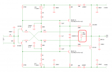
If you want to experiment then you can try placing the P3 the way shown in the schematic. In this config it will have more or less the same effect as it has in F5. 😉
Cheers and all the best.

Btw, why don't we try the vanilla V3 first? 😉
Attachments
If you want to experiment then you can try placing the P3 the way shown in the schematic. In this config it will have more or less the same effect as it has in F5. 😉
Cheers and all the best.
Btw, why don't we try the vanilla V3 first? 😉
Thanks a lot.
You're welcome!
Just some thoughts about the trimmer (P3). In my experiments I found it to be very easy to make the amplifier produce a lot of even harmonics (not just the second harmonic) with the help of the trimmer. But the point at which distortion (mainly even-order components) measured lowest was when the trimmer was exactly at mid-point, i.e. providing equal resistance in both FB paths. At the end of the day the realization was that other than deliberately increasing distortion, the trimmer has no purpose, at least in PeeCeeBee.
🙂
You're welcome!
Just some thoughts about the trimmer (P3). In my experiments I found it to be very easy to make the amplifier produce a lot of even harmonics (not just the second harmonic) with the help of the trimmer. But the point at which distortion (mainly even-order components) measured lowest was when the trimmer was exactly at mid-point, i.e. providing equal resistance in both FB paths. At the end of the day the realization was that other than deliberately increasing distortion, the trimmer has no purpose, at least in PeeCeeBee.
🙂
cool that you already tried a "p3".
I was looking for reduce 2nd order harmonics.
how the biasing works ? what is the recomended biasing?
Thanks.
cool that you already tried a "p3".
I was looking for reduce 2nd order harmonics.
how the biasing works ? what is the recomended biasing?
Thanks.
Hi brunogiovs.
Input and VAS biasing is done primarily by two 15K resistors sourcing and sinking current to and from the input BJTs' emitters.
Only VAS bias needs to be monitored/trimmed to ~10mA by the two 2K2 trimmers which also help trim the output offset.
Output MOSFET bias is auto-set to between 150-200mA by the two 1N4148 diodes.
That's all really. 🙂
So If replace de diodes I can get 30-50ma. did you or someone already measured with a lower biasing?
Thanks
So If replace de diodes I can get 30-50ma. did you or someone already measured with a lower biasing?
Thanks
We Did!
You can short one of the diodes and get 30-50mA right-away.

(edit: The V2 PeeCeeBee runs at 30-40mA bias per MOSFET. You can follow the links in my signature to get to it fast.)
Last edited:
We Did!
You can short one of the diodes and get 30-50mA right-away.
(edit: The V2 PeeCeeBee runs at 30-40mA bias per MOSFET. You can follow the links in my signature to get to it fast.)
thanks.
V3 Gerbers
Hello Guys!
Here are the Gerber files for V3 PeeCeeBee. Hopefully these will make local printing easier for those whose PCB-plants don't accept PDFs.
These have been checked with gerber-viewer.com's online viewer and seemed okay to me. If anyone finds a mistake, let me know.
Happy DIYing to all.
shaan
Attachments
Did anybody tried those mosfets ? I suspect they are good mosfet replacements?
ECX10N20/ECX10P20
http://www.profusionplc.com/pro/gex/pcatdtl0.html
ps. I tried these on my ESP P101
ECX10N20/ECX10P20
http://www.profusionplc.com/pro/gex/pcatdtl0.html
ps. I tried these on my ESP P101
Last edited:
You can use them in PeeCeeBee without any problem! 🙂
edit: PeeCeeBee doesn't have gate ESD protection zener diodes as the 1058/162 pair MOSFETs have them integrated. If you use the MOSFETs you mentioned then add 12V zeners between gate and source of each device.
edit: PeeCeeBee doesn't have gate ESD protection zener diodes as the 1058/162 pair MOSFETs have them integrated. If you use the MOSFETs you mentioned then add 12V zeners between gate and source of each device.
Last edited:
After some days listening with Olafs clever 1.0 boards i enjoy more the simple vssa.
Choose good parts build and enjoy.
I was a bit reading back and found the way how to came to different bias point- good explained by Olaf too.
What is the reason to add 1 Ohm resistors in V3?- i think it's written here and sorry for asking again.
Choose good parts build and enjoy.
I was a bit reading back and found the way how to came to different bias point- good explained by Olaf too.
What is the reason to add 1 Ohm resistors in V3?- i think it's written here and sorry for asking again.
- Home
- Amplifiers
- Solid State
- PeeCeeBee