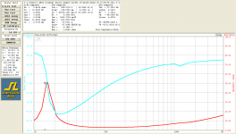
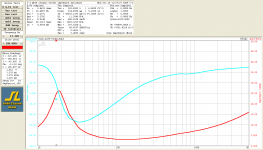
I forgot to mention that I stumbled on some measurements of the AR3 woofers on the classic speakers forum...Not sure how the AR3 woofer differs..
The woofer parameters look reasonably close to those for the AR woofer.
Thiele-Small parameters for early AR 2* and AR 3* - Acoustic Research - The Classic Speaker Pages Discussion Forums
Attachments
I agree, you should be able to work a piezo into the Sony circuit with a few changes to the compensation scheme. Of course when it comes to producing a stable feedback network around a mechanical device...the devil is in the details. As you had mentioned, first step will be to get the woofer in a sealed enclosure. Second step will be to get some information on the open loop response....I compare the Sony MFB circuit to the circuit on the preamp from my servo loudspeakers that I have tried to figure / trace out (some values missing so far).
A few questions/comments on your servo circuit ideas:
1) As drawn, the piezo buffer is operating in voltage mode, with input impedance of 440K. The piezo used must have a fairly high capacitance to avoid rolling off the lows from the sensor too early. Do you know what it is? Or can you measure it?
2) Is C1= 0.47uF? or 0.47nF? If it is 0.47nF, then U2 is acting as a LP filter, rolling off the highs above 1.5kHz. If it is 0.47uF, then U2 is acting as an integrator, putting a slope in the response above 1.5Hz. My guess is that it is 0.47nF, since you don’t want an integrator between the piezo and mixer unless it is part of a piezo charge mode buffer.
So, if you use X4 as a voltage mode buffer for your piezo, you should NOT modify X1 into an integrator.
R12 and C10 can be modified as needed to provide any HF roll-off desired in the pre-mixer signal. With the values shown, the LP filter starts rolling off highs above 340Hz…you probably will want to move that up an octave or two depending what sort of HF cone break-up or sensor resonance you need to avoid.
3) Can you determine what values Ra, C2, and C3 have?
4) You mention another bandpass circuit coming after the mixer…any idea what the pass band is set for? Seems odd that a bandpass would be used inside the loops since it would cause phase shifts that reduces phase margin at both HF and LF.
4) Had you looked at removing the 40Hz boost of +6dB and extending the LF response of the Sony pre-amp as mentioned in second paragraph of Post#432 ?
Last edited:
Bolserst - Thanks for the enlightening analysis! It will be after this Friday when I can get back at it to try to ferret out more details on the piezo servo circuit and also look into your idea of removing the bass boost in the sony.
Many thanks.I forgot to mention that I stumbled on some measurements of the AR3 woofers on the classic speakers forum.
B.
Very interesting posts here, thanks.
The conclusion is not very encouraging.
To get good results from a velocity servo-driver, you must either limit the amplitude of the cone to avoid large Bl variations or to choose a driver having a very linear Bl and/or a special suspension to avoid the phenomenon known as instability of drivers that you expound. Such drivers are uncommon and necessarily expensive.
It is somewhat paradoxal that, in an attempt to linearize a driver with velocity feedback, one must begin with an already very linear or specialized driver.
This is not the case with acceleration sensors. However the problem with them is the tying on the cone. All DIY projects seem to be limited because of a mechanical resonance, the sensor needs a mechanical decoupling. I think it can solved only at the industrial stage, not by a diyer at home with some kind of glue. Maybe, one day, drivers with acceleration sensors will be avaivalable on the market, it was the case about twenty five years ago with products of Philips origin.
Many people, after having tried to build servo-ed loudspeakers, that the Linkwitz or other kind of transforms is the reliable way to go to (apparently) modify the fc and Qtc parameters of drivers.
Very true, using the voice coil as its own velocity sensor is questionable. It's hard to isolate the pure velocity component v(t) from the voltage drop accross the static impedance Zs (which isn't static, actually) and, more importantly, once the coil is pulled out of the gap this "microphonic voltage" is giving a wrong signal, less than actual velocity: Measuring veloctity via the equation Terminal Voltage = BL*v(t) + i(t)*Zs requires that BL is a constant (as well as Zs).
This leads to the surprising effect that the drop of BL causes way too much force injected because the force factor has decreased (but it still is inside of corrective feedback so this has no effect on the closed loop). Cone showns massive overshoot (expanding odd order distortion) once it leaves the gap and that is a disaster unless you have a limiter/clipper ahead and/or a very progressive suspension that limits the excursion (by essentially dropping system loop gain to actually disable the feedback) and/or little feedback at work to start with.
In modern drivers with very low Qes this overshoot from too much self-MFB is also happening and (hopefully) the designers chose a suspension that perfectly compliments this so that total linear excursion is maximized and overshoot is definitely eliminated. In fact by choosing a proper drive impedance you can adjust this large-signal distortion mechanism in a certain range, that is you can shape the "distortion knee" somewhat.
The conclusion is not very encouraging.
To get good results from a velocity servo-driver, you must either limit the amplitude of the cone to avoid large Bl variations or to choose a driver having a very linear Bl and/or a special suspension to avoid the phenomenon known as instability of drivers that you expound. Such drivers are uncommon and necessarily expensive.
It is somewhat paradoxal that, in an attempt to linearize a driver with velocity feedback, one must begin with an already very linear or specialized driver.
This is not the case with acceleration sensors. However the problem with them is the tying on the cone. All DIY projects seem to be limited because of a mechanical resonance, the sensor needs a mechanical decoupling. I think it can solved only at the industrial stage, not by a diyer at home with some kind of glue. Maybe, one day, drivers with acceleration sensors will be avaivalable on the market, it was the case about twenty five years ago with products of Philips origin.
Many people, after having tried to build servo-ed loudspeakers, that the Linkwitz or other kind of transforms is the reliable way to go to (apparently) modify the fc and Qtc parameters of drivers.
Strange to have the special case of Xmax drive the discussion. Like in other sub forum discussions, extravagant loudness seems a bigger focus than everyday loudness. I can't say how often I come close to max excursions - maybe I often do but don't know it. But I doubt it, or it is rare like other forms of exceeding design limits.To get good results from a velocity servo-driver, you must either limit the amplitude of the cone to avoid large Bl variations
Granted, VC feedback gets into trouble at Xmax, but what about the bad things that happen at Xmax with accelerometer feedback? I bet you are in just as much hot water either way.
Ben
I agree. But, the aim of servoing is the reduction of distorsion. And at small cone excursions, the distorsion is low.Strange to have the special case of Xmax drive the discussion. Like in other sub forum discussions, extravagant loudness seems a bigger focus than everyday loudness. I can't say how often I come close to max excursions - maybe I often do but don't know it. But I doubt it, or it is rare like other forms of exceeding design limits.
The accelerometer gives an accurate information of the cone movement whatever it is.Granted, VC feedback gets into trouble at Xmax, but what about the bad things that happen at Xmax with accelerometer feedback? I bet you are in just as much hot water either way.
Velocity sensed by a bridge or one of the coils of a dual voice coil driver do not (I do not know how the Rythmik drivers with their dedicated sensing coil behave from this point of view).
However the Xmax behavior as described by KSTR can be cured using current drive. But then the velocity feedback loop has the job to restore the damping (Q) !
I wonder il all these problems could be solved by applying the servoing action only to subwoofers low-pass filtered at 80 Hz and having a main resonance at 80 Hz.
Many people, after having tried to build servo-ed loudspeakers, that the Linkwitz or other kind of transforms is the reliable way to go to (apparently) modify the fc and Qtc parameters of drivers.
I should have written :
Many people, after having tried to build servo-ed loudspeakers, think that the Linkwitz or other kind of transforms is the reliable way to go to modify the apparent fc and Qtc parameters of drivers.
Last edited:
Yes, that's the theory. But we need to ask what happens at the extremes of motion what funny things happen to magnetics and suspensions and phases, etc?The accelerometer gives an accurate information of the cone movement whatever it is.
I'd say the main issue is: does the system inhibit self-destruction even at Xmax. That's all we need do, not fret about distortion at Xmax.
Ben
I tested my MFB system at both low and high volumes, and at both low and high frequencies.VC feedback gets into trouble at Xmax, but what about the bad things that happen at Xmax with accelerometer feedback? I bet you are in just as much hot water either way.
I did not see any sign of the piezo accelerometer approach being "in hot water" at high excursion. Closed-loop harmonic distortion was always much less than open-loop harmonic distortion, even at high powers and large excursions. With 18 dB of feedback, I actually saw nearly 18 dB of 3rd harmonic reduction at some frequencies. (The amount of feedback was less than 18 dB at some other frequencies, and, of course, so was the reduction in THD.)
This reduction in THD is the acid test - if you see substantial distortion reduction, then the negative feedback is working properly, and doing what it's supposed to, and that means its getting a good feedback signal.
Keep in mind all this was obtained with my home-brewed piezo accelerometer - an ordinary piezo disc of the sort used in a million beepers and buzzers - and a home-brewed piezo mount, albeit one that I used a lathe to make.
I'm not surprised that the piezo was very linear - not because piezo's are magically perfect sensors, but because, in this case, the piezo disc was only experiencing very, very tiny deformations. We're talking about a half-inch piezo disc that was rigidly supported all the way around its edge, after all. Any deflections must have been truly microscopic.
That was in the late 1990's. I would have expected that, these days, there would be cheap analogue MEMS accelerometers that were very linear to +/- 100 G's or so, and there would be no reason to futz around with relatively heavy piezo discs.
Am I wrong? Are there no such sensors around?
-Gnobuddy
I tested my MFB system at both low and high volumes, and at both low and high frequencies.
I did not see any sign of the piezo accelerometer approach being "in hot water" at high excursion.
No, I meant when the corrected signal gets back to the VC. Since it is in no-person's-land (at Xmax and beyond), who can say how the cone will react, phase, etc. The whole system is in the loop and if any one part is outside its operating range, you are in hot water.
B.
Back in 1980'Th I made for myself a subwoofer from a bass guitar cabinet, gluing a piezo crystal to the speaker coil, with a JFET. I had a 6 db/Oct boost for a feedback by acceleration. It worked great, it was very hard to push the cone by hand. However, I forgot about a rumble filter, so when I put the first vinyl disk with Bach organ record, the amp spit the cone off completely trying to reproduce the result of non-concentric record on the Soviet disc. I did not have a replacement driver, so installed a pair of 10" drivers instead of 15" one, and added to the amp a positive feedback by current. It was the first and last experiment I did with a mechanical feedback... 😀
Ah. True, feedback can't get blood from a stone, to mis-quote a very old saying. 🙂No, I meant when the corrected signal gets back to the VC. Since it is in no-person's-land (at Xmax and beyond), who can say how the cone will react, phase, etc. The whole system is in the loop and if any one part is outside its operating range, you are in hot water.
B.
It might not be a bad idea to incorporate some sort of sensing electronics to tell the user when the system is reaching it's limits. Measuring the difference between the woofer drive signal, and a suitably amplified copy of the input, may be sufficient.
If the woofer behaves perfectly, that difference signal will be zero; the more trouble the woofer gets into, the bigger that error signal will be. If it gets big enough, light up a warning LED, or even cut the input signal appropriately. A 10 dB drop should serve both as protection and to let the user know to turn down the subwoofer.
-Gnobuddy
I wonder what the cannon-shots in a recording of Tchaikovsky's 1812 Overture would do. 😱However, I forgot about a rumble filter, so when I put the first vinyl disk with Bach organ record, the amp spit the cone off completely trying to reproduce the result of non-concentric record on the Soviet disc.
-Gnobuddy
Hi Y'all,
Here are two patents that caught my eye:
The BagEnd ELF system patent has a limiter circuit to prevent overexcursion. That may be more generally applicable:
4,481,662
And on the subject of mixing feedbacks: Rythmik uses a combination of sensing resistor and sensing coil:
8,031,882
Don't know if this helps, you are so far ahead of me... 🙂.
Regards,
It might not be a bad idea to incorporate some sort of sensing electronics to tell the user when the system is reaching it's limits. Measuring the difference between the woofer drive signal, and a suitably amplified copy of the input, may be sufficient.
On AES back in 2008 in San Francisco I saw small enclosures that were going pretty low, because of an electret microphone glued inside, as a pressure sensor.
Intriguing. I would have thought most electret mics would overload massively long before the woofer did, considering the SPL levels microphones are designed for....an electret microphone glued inside, as a pressure sensor.
I once had a pair of Maxell noise-cancelling headphones that used a tiny electret microphone capsule inside the ear cups to pick up the sound, and provide true motional feedback. They had the best bass I've ever heard from headphones - deep, crisp, solid, tight, absolutely no boominess.
-Gnobuddy
Thanks for sharing!The BagEnd ELF system...has a limiter
I'm not familiar with this system, but I think limiters of some sort on powerful subwoofers are probably a pretty good idea.
So we have a mixture of two really poor-quality feedback signals, neither of which actually represents cone motion very well, both trying to correct for a problem they are unaware of.And on the subject of mixing feedbacks: Rythmik uses a combination of sensing resistor and sensing coil
That reminds me of the Sears and Kmart business merger some years ago. Two failing businesses, somehow hoping that merging would solve both their problems. 😀
-Gnobuddy
Intriguing. I would have thought most electret mics would overload massively long before the woofer did, considering the SPL levels microphones are designed for.
...and it was my first thought! I asked the guy, how do they protect microphones from too high pressure, he said that they do not! Then I asked if I can steal the idea, he said, "Yes!" 🙂
But I still did not try it...
Apparently the issue of woofer cone excursion limiting has been popular on diyAudio lately: http://www.diyaudio.com/forums/pc-based/298248-sensorless-dsp-cone-excursion-limiter.html
-Gnobuddy
-Gnobuddy
The Kii speaker has a clever protection scheme. An analog circuit ahead of the DSP looks at the signal, and if illegal demands are made, DSP-slopes are adjusted.
More about the Kii early next year in AudioXpress, which will carry a review with anaechoic measurements et al. by Jan Didden and me.
More about the Kii early next year in AudioXpress, which will carry a review with anaechoic measurements et al. by Jan Didden and me.
- Home
- Loudspeakers
- Subwoofers
- Commercial motional feedback woofer available sort of