Thanks Hugh!Nice figures, Thimios!
Valery, do you think phase shift at 20KHz is important to the sound quality?
I strive for 3 degrees or less but I often wonder how this attempt brings benefits.......
Hugh
My pleasure to see you here.
I can't see competition available, only cooperation.
Congratulations!
A true gentleman!🙂
Nice figures, Thimios!
Valery, do you think phase shift at 20KHz is important to the sound quality?
I strive for 3 degrees or less but I often wonder how this attempt brings benefits.......
Hugh
Hi Hugh,
For me, phase shift at 20KHz is one of the indirect indicators of overall design quality. I also try to keep it somewhere between 2-4 degrees - as flat as possible throughout the audio bandwidth. The most natural-sounding amplifiers usually have it this way, according to my experience.
Some 8-12 degrees phase shift at 20KHz is most likely a result of certain over-compensation (leading to low ULGF, slowed-down step response, higher distortion at 20 KHz). Then the logical question is - why did the designer reach this kind of conditions? Some issues with stability margins? Particularly limited bandwidth of the output stage? Makes me suspicious 🙄
Cheers,
Valery
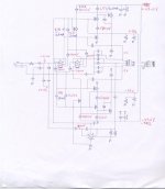
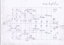
vfa circuit details
Useful for debugging.
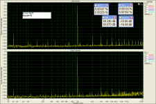
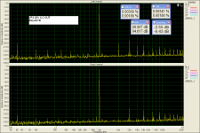
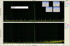
Coming soon,distortion measurements.
Useful for debugging.
Coming soon,distortion measurements.
Attachments
Last edited:
Useful for debugging.
Coming soon,distortion measurements.
Thank you! Runs well - LTPs are balanced, operating points - as designed

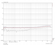
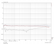
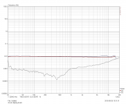
VFA DISTORTION
Please do not see the absolute values.
This is what my soundcard measured.
Amplifier distortion will be even lower.
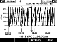
Last picture shows the variable voltage output during the test(steps) in clip conditions.
Please do not see the absolute values.
This is what my soundcard measured.
Amplifier distortion will be even lower.
Last picture shows the variable voltage output during the test(steps) in clip conditions.
Attachments
-
 VFA.PNG94.5 KB · Views: 356
 -
 VFA 20V A.C -2.5db.PNG93.7 KB · Views: 328
 -
 VFA -20db.PNG94.5 KB · Views: 345
 -
 vfa 12v a.c out.PNG66.2 KB · Views: 322
 -
 vfa 29v a.c out.PNG66 KB · Views: 148
 -
 vfa at clipping levels.PNG65.5 KB · Views: 170
 -
vfa clipping 1.bmp9.4 KB · Views: 125
-
 vfa clipping 1.PNG2.1 KB · Views: 168
Last edited:
VFA+NS DISTORTION
Using Right Mark.
Using Right Mark.
Attachments
-
 DETAILS.PNG22.6 KB · Views: 192
 -
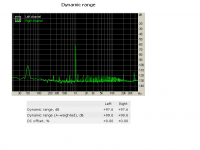 DYNAMIC RANGE.PNG27.3 KB · Views: 176
 -
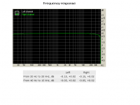 FREC RES.PNG23 KB · Views: 154
 -
 IMD SWEEP TONES.PNG19.3 KB · Views: 150
 -
 INTERMODULATION DISTORTION.PNG28.5 KB · Views: 149
 -
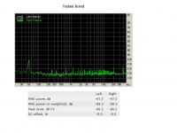 NOISE LEVEL.PNG28.2 KB · Views: 141
 -
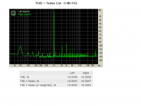 THD+NOICE.PNG28.1 KB · Views: 162
 -
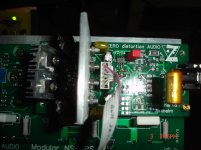
 DSC08329.jpg280.9 KB · Views: 192
Last edited:
Thimios,
Too old to compete with anyone now, just with myself.......
Valery, your use of a twin triode for the LTP puts the tube overlay into the fb loop and therefore diminishes the sound of a tube. I think you identified this recently, and I agree.
To overlay the tube sound a little stronger, you could put the triode in front, as a CF perhaps outside the fb loop.
Have you tried this? Of course in my GK1 this does this; the preamp output stage is a CF and worked well....
Cheers,
Hugh
Using Right Mark.
Looks very good to me. So, you've got all 3 front-end board options operational now, right? Vertical CFA + VFA and X4. Cool 😎
Thimios,
Too old to compete with anyone now, just with myself.......
Valery, your use of a twin triode for the LTP puts the tube overlay into the fb loop and therefore diminishes the sound of a tube. I think you identified this recently, and I agree.
To overlay the tube sound a little stronger, you could put the triode in front, as a CF perhaps outside the fb loop.
Have you tried this? Of course in my GK1 this does this; the preamp output stage is a CF and worked well....
Cheers,
Hugh
Hugh, you're right - I actually used the tube as a fine IPS device, not expecting the "tubish" sound in this topology. It shows very good open loop linearity in combination with low noise. Of course, this front-end topology also works with jFETs and BJTs (tested with 2sk117 and BC546 pairs, with appropriate degeneration for each variant). But I still like the tube option very much - it glows and gives a feeling of very high clarity 🙂
Cheers,
Valery
Yes,CFA+VFA and X4 are ready and tested.Looks very good to me. So, you've got all 3 front-end board options operational now, right? Vertical CFA + VFA and X4. Cool 😎
I will try to change some resistor values in X4 making this run cooler .I haven't smd resistors,so i will try to do with thru hole parts.
BTW here is the OUTPUT measurements,just in case that will be useful to someone for debugging.
Attachments
Last edited:
I will try to change some resistor values in X4 making this run cooler .I haven't smd resistors,so i will try to do with thru hole.
This is possible by simultaneous increase of the values of LTPs' tail resistors and resistor between the VAS output current mirrors (3 values in total).
On schematic in post #754 those are: R37, R38, R21.
First - set the VAS output current with R21.
Then - adjust the currents through Q3, Q5, Q7, Q8 with R37, R38.
All these currents have to be roughly the same for the best performance.
Voltage drop over R4, R5, R15, R16 is twice as much, comparing to the voltage drop over R8, R9, R14, R19.
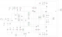
You have publised an update shematic in post#1158.
Is it ok to start with?
Right! Sorry, forgot about it. Here it is once again - just to avoid any confusion.
So, R24 || R95 set the VAS idle current.
Then R6, R15 set the currents through Q3, Q4, Q5, Q6 equal to that VAS idle current. The values, shown here, are calculated for the VAS idle current of around 5mA - this is what you are actually looking for.
Attachments
looks like the CFA front end favors 2nd order over 3rd order harmonics. At this low a level of distortion I wonder if this would sound different then the other front end options that seem to favor 3rd order.
I will try to explain farther.looks like the CFA front end favors 2nd order over 3rd order harmonics. At this low a level of distortion I wonder if this would sound different then the other front end options that seem to favor 3rd order.
In all the IPS except CFA the input gnd separeted from main gnd with a 10R smd resistor.
To keep all gnd the same (not smoke)when testing i short this resistor.
Now the important notice...Testing the VFA or X4 with this resistor shorted the distortion figure is equal to the CFA one!
Last edited:
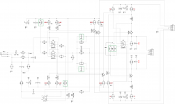
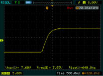
vz-x4 lower VAS current
Ok,here we are.
According to this schematic.
The only difference the compensation capacitors. 47pf has been installed in position C12,C13
Vas current is now 6mA and amplifier runs faster,640ms rise time(smaller compensation).
Full test coming soon.
Right! Sorry, forgot about it. Here it is once again - just to avoid any confusion.
So, R24 || R95 set the VAS idle current.
Then R6, R15 set the currents through Q3, Q4, Q5, Q6 equal to that VAS idle current. The values, shown here, are calculated for the VAS idle current of around 5mA - this is what you are actually looking for.
Ok,here we are.
According to this schematic.
The only difference the compensation capacitors. 47pf has been installed in position C12,C13
Vas current is now 6mA and amplifier runs faster,640ms rise time(smaller compensation).
Full test coming soon.
Attachments

Last edited:
modified vz -x4 test
Let's go!
Let's go!
Attachments
-
 100KHz sq.PNG14.8 KB · Views: 181
 -
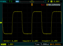 50KHz sq.PNG13.8 KB · Views: 147
 -
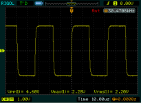 30KHz sq.PNG14.7 KB · Views: 144
 -
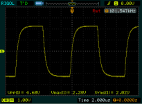
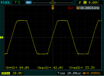
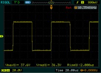
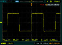
 20KHz sq.PNG14.2 KB · Views: 155
 -
 10KHz sq.PNG14.1 KB · Views: 152
 -
 1kHz squarwave.PNG13.9 KB · Views: 145
 -
 VZ 20KHz CLIP.PNG16.6 KB · Views: 138
 -
 VZ 10KHz CLIP.PNG14.4 KB · Views: 125
 -
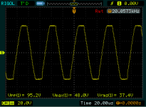
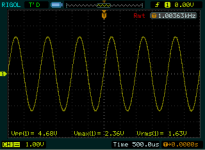
 10KHz before clip.PNG13.3 KB · Views: 153
 -
 1Khz low level.PNG16.6 KB · Views: 194
modified vz -x4 test
The rest.
Full Power,10KHz,20KHz just before clip.
The rest.
Full Power,10KHz,20KHz just before clip.
Attachments
Last edited:
Looks excellent!
I think, we will add one more resistor placeholder in series with both both R6 and R15 - the optimal value would be some 5.8...5.9 Kohm - easier to add-up by 2 resistors.
It's pretty well-balanced by itself - only 56mV at the servo output, easy job for the servo.
I think, it's going to become our "flagship" IPS board for Modular series.
Is the front-end running cooler in terms of temperature, just by touching the local heatsinks?
- Home
- Amplifiers
- Solid State
- Revisiting some "old" ideas from 1970's - IPS, OPS