I can't repeat the phenomenon.
I have try hard but no success.
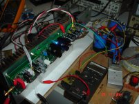
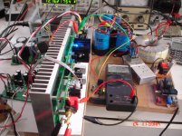
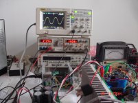
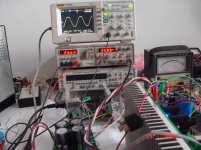
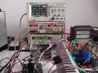
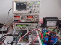
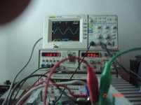
Now it's time for test.
CFA IPS.
+/-50V
74000uf/Rail
idle current 65mA.
R load =7R.
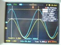
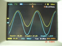
Sinusoidal
I have try hard but no success.
Now it's time for test.
CFA IPS.
+/-50V
74000uf/Rail
idle current 65mA.
R load =7R.
Sinusoidal
Attachments


Last edited:
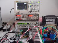
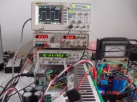
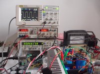
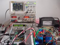
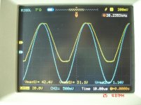
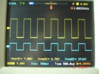
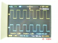
Square wave.
Attachments
-
 DSC08263.jpg328.7 KB · Views: 134
 -
 DSC08262.jpg322.9 KB · Views: 146
 -
 DSC08258.jpg334 KB · Views: 158
 -
 DSC08264.jpg316.7 KB · Views: 144
 -
 DSC08265.jpg327.2 KB · Views: 138
 -
 DSC08267.jpg336.5 KB · Views: 138
 -
 DSC08273.jpg324.1 KB · Views: 153
 -
 DSC08271.jpg304.1 KB · Views: 137
 -
 DSC08270.jpg309.8 KB · Views: 134
 -
 DSC08274.jpg309.9 KB · Views: 153
Last edited:
It's nice to hear the bias issue isn't returning. I would reflow all the solder joints on the boards that were having the original issue. Cold or cracked solder joints can disconnect and reconnect with temperature change/expansion. I see this all the time in automotive applications with the extreme temperatures and vibration.
I hope for VFA test finalizing today or tomorrow😉Good! Thimios, thanks a lot for the pictures 😎
Jeff, i don't believe that is a matter of a dry solder....It's nice to hear the bias issue isn't returning. I would reflow all the solder joints on the boards that were having the original issue. Cold or cracked solder joints can disconnect and reconnect with temperature change/expansion. I see this all the time in automotive applications with the extreme temperatures and vibration.
I have doubts about these new old stock non inductive resistors. Some of them have pins not so consistently and they stretched a bit in this pcb.
Jeff, i don't believe that is a matter of a dry solder....
I have doubts about these new old stock non inductive resistors. Some of them have pins not so consistently and they stretched a bit in this pcb.
That's quite possible too. Did I send emitter resistors along with the parts? If so they would be non-inductive IRC resistors. CAW5R220JLF INTERNATIONAL RESISTIVE, Through Hole Resistor, Ceramic, 0.22 ohm, Axial Leaded, 5 W, ± 5%, CAW Series, Newark element14 Canada
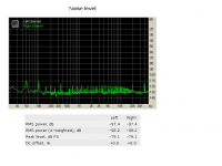
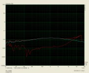
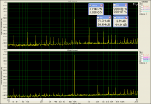
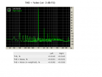
CFA IPS distortion
First group Right Mark.
First group Right Mark.
Attachments
-
 thd+noise.PNG28.4 KB · Views: 152
 -
 noise.PNG26.4 KB · Views: 148
 -
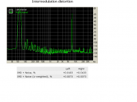 intermodulation distortion.PNG28.5 KB · Views: 154
 -
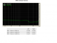 imd swept.PNG21.4 KB · Views: 140
 -
 frec resp.PNG22.1 KB · Views: 158
 -
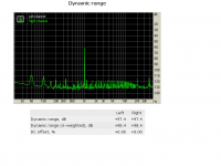 dynamic range.PNG28.2 KB · Views: 180
 -
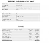 details.PNG22.8 KB · Views: 190
 -
 cfa zero distortion modular -7db.PNG65 KB · Views: 164
 -
 modular cfa 1.PNG90.8 KB · Views: 175
Last edited:
For the Right Mark?These ones are not 100% clear 🙂
What are the output swings (RMS)?
It is at -1db
Right, but to understand the scale, I need to know what RMS voltage corresponds to this -1db level. How many volts AC RMS at 8 ohm load.
Sorry Valery,i don't know,i seen that is just under clip level,but i will measure if it is necessary to know the exactly value😉Right, but to understand the scale, I need to know what RMS voltage corresponds to this -1db level. How many volts AC RMS at 8 ohm load.
P.S i think that is about 25v/7R(this is the clip level according to sinusoidal test).
Last edited:
Sorry Valery,i don't know,i seen that is just under clip level,but i will measure if it is necessary to know the exactly value😉
P.S i think that is about 25v/7R(this is the clip level according to sinusoidal test).
It makes sense to measure at some intermediate level - say, 20V RMS at the load. Close to clipping you see some higher distortion - which is also interesting to see, but it's a kind of close to the edge.
It would make sense to gust connect the oscilloscope to the output and calibrate the output swing of the sound card to the desired level.
This will be interesting.
1) the vz-x4
2) CFA
3)vz-x4
4) CFA
Same total power levels.
1) the vz-x4
2) CFA
3)vz-x4
4) CFA
Same total power levels.
Attachments


Last edited:
This will be interesting.
1) the vz-x4
2) CFA
3)vz-x4
4) CFA
Same total power levels.
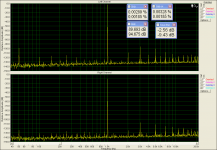
OK - that's what I meant - nominal 0db level is a bit too high 😉
At -10db they are rather close to each other with THD below 0.002%
At -3db, CFA's distortion becomes around 10 times higher - because it clips earlier, I think.
X4 is very cool - consistent performance at any swing.
Ok the vz-x4 distortion at -10db has been posted here. http://www.diyaudio.com/forums/soli...-old-ideas-1970s-ips-ops-130.html#post4828204OK - that's what I meant - nominal 0db level is a bit too high 😉
At -10db they are rather close to each other with THD below 0.002%
At -3db, CFA's distortion becomes around 10 times higher - because it clips earlier, I think.
X4 is very cool - consistent performance at any swing.
#post 1297.
I will test the CFA at -10db and i will post again these two files for comparision.
Last edited:
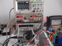
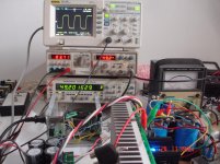
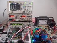
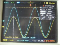
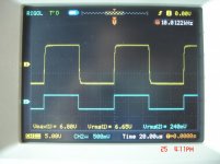
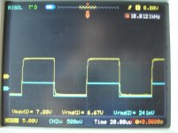
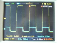
VFA+NS OUTPUT
+/-50v
74.000uf/rail
idle current=65mV
Rload=7R
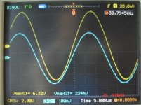
Yellow is the output signal
Blue is the input signal.
+/-50v
74.000uf/rail
idle current=65mV
Rload=7R
Yellow is the output signal
Blue is the input signal.
Attachments

Last edited:
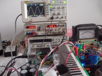
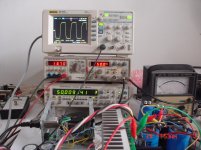
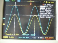
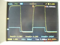
VFA+NS OUTPUT
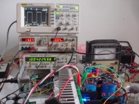
Square wave
Square wave
Attachments


Last edited:
OK - looks stable, clean, pretty fast for VFA, clipping at 20KHz is very decent (at 1KHz it would be very soft and clean) . Phase shift at 20KHz is rather low (my precise measurements showed something below 4 degrees) 
Nice figures, Thimios!
Valery, do you think phase shift at 20KHz is important to the sound quality?
I strive for 3 degrees or less but I often wonder how this attempt brings benefits.......
Hugh
Valery, do you think phase shift at 20KHz is important to the sound quality?
I strive for 3 degrees or less but I often wonder how this attempt brings benefits.......
Hugh
- Home
- Amplifiers
- Solid State
- Revisiting some "old" ideas from 1970's - IPS, OPS