I build another PCB, this time with NSL-32SR3 instead of SR2. Not only that it worked, there is also no volume bump in the middle.
ZDR,
Did you notice any other difference when using the NSL-32SR3, or have to make any changes to use the NSL-32SR3 ?
Regards
Downunder55
It's more difficult to calibrate, it fails often. No changes made. It's supposed to have lower distortion than sr2.
Sent from my SM-G935F using Tapatalk
Sent from my SM-G935F using Tapatalk
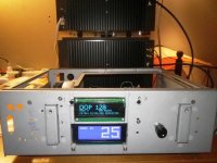
I have now one fully assembled and operational VxD with SR3. It failed to calibrate on first attempt, but calibrated on 2nd with 50 volume steps. There is no volume bump in the middle like I have with other two setups with SR2. It seems that LDR resistance is more unstable at >500K range, but VxD is not operating in that area anyway afaik.

Hi all ,
there is any left board 2 or 3 inputs to 1 or 2 outputs for Latching relays AGQ21012
BR Nikos
there is any left board 2 or 3 inputs to 1 or 2 outputs for Latching relays AGQ21012
BR Nikos
I have few left, 4in 2out, single ended. See my earlier post for photo.
Sent from my SM-G935F using Tapatalk
Sent from my SM-G935F using Tapatalk
I tried with 60 steps, and the hump moved to step 29-30. This looks like a problem with the middle step.
Hi Neb this humb do you see it on the Osc only ,or do you heard also ?
I see it only on the Osc.
Also, the noise problem I had solved, i forgotten to put the Gnd from PSU to chassis.
Attachments
Last edited:
Hi Neb this humb do you see it on the Osc only ,or do you heard also ?
I see it only on the Osc.
Also, the noise problem I had solved, i forgotten to put the Gnd from PSU to chassis.
I can hear it with white noise easily. Didn't try the scope, but it will probably show there too. I don't hear it with SR3 LDRs.
Hi zdr,
do you have any 3in boards by Vincent, like the one in post #439 ?
No sorry, sold long time ago.
It's supposed to have lower distortion than sr2.
Thats only because the sr3 can't attenuate as low as the SR2S at 20mA
40ohms typical for the sr2s
150ohms typical for the sr3.
Distortion is minimal .01 2hd at source levels, your speaker/amp distortions are huge compared to that.
Cheers George
Thats only because the sr3 can't attenuate as low as the SR2S at 20mA
40ohms typical for the sr2s
150ohms typical for the sr3.
Distortion is minimal .01 2hd at source levels, your speaker/amp distortions are huge compared to that.
Cheers George
From first page of this thread:
"- the LDR LEDs are working at low current (7 mA maximum), they will last a very long time"
So at the max current, there is negligible difference in resistance between the two, typically around 40 ohm. But the difference in distortion is negligible too, I agree.
There is no volume "bump" however with two SR3 builds I completed. Both SR2 builds I've done have it.
Not big enough sample for conclusion though.
But can you get down to 40ohms with just 7mA, I think not
My prototype has been on now 24/7 for over 10 years now with a max of 20mA, and is as a good today as it was 10 years ago, never even needing to be re-calibrated. So Silonex were correct, in giving them a safe operating 20mA current limit. But I do say in the instructions if not being used and left powered up, leave the volume at half, this way they only get 10mA
The volume "bump" in the sr2s is utilized with me as it mimics almost the volume progression of a logarithmic pot.
As the way it is, it has very slow progression from zero to around 1.30 to 2 o'clock then increases quite fast to full, just like a logarithmic pot does.
Cheers George
But can you get down to 40ohms with just 7mA, I think not
My prototype has been on now 24/7 for over 10 years now with a max of 20mA, and is as a good today as it was 10 years ago, never even needing to be re-calibrated. So Silonex were correct, in giving them a safe operating 20mA current limit. But I do say in the instructions if not being used and left powered up, leave the volume at half, this way they only get 10mA
The volume "bump" in the sr2s is utilized with me as it mimics almost the volume progression of a logarithmic pot.
As the way it is, it has very slow progression from zero to around 1.30 to 2 o'clock then increases quite fast to full, just like a logarithmic pot does.
Cheers George
George, I am not absolutely sure but I think the design yields about 150ohm shunt @ 7ma. At low volumes the series ldr resistance is additionally increased to still enable reasonable attenuation with 150 ohm shunt. In other words the design does not resemble a nominal ~10K (or whatever you nominate in the software) pot in these situations (more like 50k+).
Last edited:
- Home
- Source & Line
- Analog Line Level
- Arduino based LDR volume and source selection controller