I use op amps, have for the last 50 years, since they were first developed. I have always found discrete circuits, IF DESIGNED PROPERLY, to be slightly better than any IC that I can design with. However, if discrete circuits are put together in an amateurish fashion, with little regard for optimum linearity, and just adding stages to get more feedback, then you might as well use a good IC and save yourself the trouble.
You will find that several contemporary designers like Charles Hansen of Ayre, Nelson Pass or myself, often use low feedback designs, rather than op amps in our best designs for audio. We only use IC's for our cost effective stuff. The reasons that IC's are not as good as a good discrete design are too numerous to explain in one paragraph. Maybe later.
You will find that several contemporary designers like Charles Hansen of Ayre, Nelson Pass or myself, often use low feedback designs, rather than op amps in our best designs for audio. We only use IC's for our cost effective stuff. The reasons that IC's are not as good as a good discrete design are too numerous to explain in one paragraph. Maybe later.
I have nothing but a polite "Hello!" for both the cat, and his reproductive system. 😀
In my opinion, however, this particular circuit is not a cat, but rather, a lame duck. 🙂
Most cats tend to find lame ducks very interesting. But I digress. 😀
The poor performance shown by the LTSpice simulation pretty much ends the discussion. If you know a bit about analogue circuit design, you don't even need an LTSpice simulation to see the problem - it's pretty plain to see from a look at the circuit diagram.
You raised some points worthy of discussion, so let's discuss them a bit:
*) It's a pre-amp; why should it have low output impedance?
The answer is in three parts. First, the performance of the preamp should be dependable, with a reasonable load connected. If the output impedance is extremely high, this requirement cannot be met; open-loop gain, and therefore distortion and bandwidth, vary drastically with the load connected.
Second, a preamp may be called upon to drive a shielded cable. Shielded cables have significant capacitance (typically 30 pF per foot). The cable capacitance creates a low-pass filter with the preamps output impedance. Therefore, in order to ensure that the preamp performs and has adequate bandwidth properly even when connected to a cable of reasonable length, it has to have low output impedance.
Third, shielded cables have imperfect shielding. Some electrical noise and interference will make it through the shield, and arrive at the central conductor, where it will corrupt the audio signal. If the preamp has a low output impedance, it shunts (shorts out) most of this noise; a low preamp output impedance therefore reduces the amount of noise and interference that shows up at the far end of the cable.
These three reasons are so important that every preamp made for professional audio use has a very low output impedance. A hundred ohms or less isn't unusual.
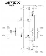
By contrast, the Apex preamp we're discussing actually has an open-loop output impedance of tens of thousands of ohms, or even hundreds of thousands of ohms, depending on output admittance (hoe) of the output devices; when the 3.3k feedback resistor is added, it actually shunts the output, and therefore drops the output impedance to about 3.3k.
Because the raw output impedance is so absurdly high, the loading from the 3.3k feedback resistor is enough to drop the open loop gain considerably. This preamp has such a high output impedance that it actually loses much of its potential performance simply from trying to drive its own negative feedback network!
You can prove this for yourself: grab the LTSpice simulation file I attached to my previous post, load it up in LTSpice, change the 3.3k feedback resistor to 220k, and watch the open loop gain leap from a rather meagre 1200 to a much more reasonable 11,000.
Think about that for a second - this preamp can't even drive its own feedback resistor without suffering drastic performance loss! Does that really seem reasonable to anyone?
*) It is "highly acclaimed as one of the better sounding products by any standard"
Unfortunately, popular acclaim is a very unreliable metric. For example, quite literally, Hitler was popular and highly acclaimed by millions. You can go on You Tube and watch video clips of old film footage showing thousands of people screaming praise and accolades at him.
Since audio electronics is an engineering field, unlike politics, we don't have to rely on popularity to tell us if a design is good or not. Instead, we simulate, build, test, and measure. If the design in question falls on its face at the very first step (simulation), there is no point proceeding further.
As I mentioned earlier, the major problem with this particular preamp implementation is the lack of an output buffer. Unfortunately, that is a major omission, a bit like building a Formula One racing car, and then putting bicycle tyres on it. You may have the high-performance engine and transmission working well, but with those bicycle tyres, you're not going to get much performance out of the car!
-Gnobuddy
Gnobuddy, you still make the same mistake in the output impedance calculation.
Do you realize the difference between loading the output with 3.3K resistor, connected to ground and 3.3K resistor connected to the negative feedback junction point?
In the latter case, you have to additionally divide it by the value, the loop gain would have had if the load had been open circuited.
The resulting value of roughly 10 ohms (at 1KHz) is more than enough for driving the power amp's input even through some rather long cable.
It will increase with frequency though, being still ok within 20KHz bandwidth.
You can easily "measure" it in your simulation:
- see RMS at the output with no external load (V);
- see RMS with R load, connected to the output (VL);
- calculate your output impedance.
Zout = R * (V / VL -1)
One more thing - in your assessment, you omit the phase response considerations completely. Increasing the feedback network's impedance for almost 2 orders (220K instead of 3.3K), you will have some phase-related issues to be addressed. Guess why.
XRK,The F1 with bicycle tire analogy is a poor one. The preamp in this case is the small electromechanical system that takes the input from the driver's foot pedal position and translates to fuel injection pulses that power the engine. The lack of low impedance drive is of no consequence. The system doesn't even need tires of any kind. The engine and tires are job of the power amp - that's where you want low inpedance drive and damping factor.
You would need a buffer if your amp has some ridiculously low input impedance like a speaker or headphones. However, most power amps fortunately have input impedances in the tens of kohms. With that load, this preamp sounds and works just fine. No buffer needed.
read Gno again. He explains why low output impedance is an advantage, three times over.
He quotes 100ohms as a good (low) value and 3k3ohms as a poor (high) value.
XRK,
read Gno again. He explains why low output impedance is an advantage, three times over.
He quotes 100ohms as a good (low) value and 3k3ohms as a poor (high) value.
Andrew, that's right, no doubt.
But Gno is wrong in output impedance calculation.
It's 10 ohm, not 3.3 Kohm here.
Hi Valery,
I read through Gno's comments, his irritation with his conviction that XRK is not correct, and his sure belief that his impeccable knowledge is correct.
Exactly as you so, the very high fb factor in this elegant design reduces the output impedance to the target amp input node to very low levels.
I would have some concerns about driving a loudspeaker through collectors, but even though seem to work very well with correct design.
Don't you love it when people criticism design correctness when they do not understand fb theory? Dunning Kruger, always worth to check it first.
X, I salute your constant activity in this forum. It's guys like you who get their hands dirty, spend on the dollars, designs the schematics and the layouts, build and listen, who make DIY what it is. I thank you for helping keep my enthusiasm.
Do you sleep?
Ciao,
Hugh
XRK,
read Gno again. He explains why low output impedance is an advantage, three times over.
He quotes 100ohms as a good (low) value and 3k3ohms as a poor (high) value.
I don't disagree that an amp or preamp with 100ohms output impedance is better at driving loads vs one with 3.3kohms impedance.
I disagreed with the analogy of making the preamp the whole "machine" as in an F1 car. It's a small subsystem that drives/controls the larger main "engine".
Nonetheless, as Valery points out, the 3.3kohm output impedance is not correct and it is actually a much lower value.
Hi Valery,
I read through Gno's comments, his irritation with his conviction that XRK is not correct, and his sure belief that his impeccable knowledge is correct.
Exactly as you so, the very high fb factor in this elegant design reduces the output impedance to the target amp input node to very low levels.
I would have some concerns about driving a loudspeaker through collectors, but even though seem to work very well with correct design.
Don't you love it when people criticism design correctness when they do not understand fb theory? Dunning Kruger, always worth to check it first.
X, I salute your constant activity in this forum. It's guys like you who get their hands dirty, spend on the dollars, designs the schematics and the layouts, build and listen, who make DIY what it is. I thank you for helping keep my enthusiasm.
Do you sleep?
Ciao,
Hugh
Hi Hugh,
Thanks for the kind words. LOL - I need to get more sleep. 😛
I actually do use and trust models and simulations in case someone is wondering why I don't take Gno's assessment that the Apex circuit that I built sucks. I generally model speakers (horns, TL's, etc) in Akabak before building. But like all simulations, they depend on the quality/accuracy of the system being modeled and the assumptions used. A couple of amps in this forum, I have used models to guide me to show that collector driven latFET gates can be used to drive vertical MOSFET gates very well. Then I am lucky enough to have someone design the layout, then I fab PCB's and then build and test. A couple of these amps (FH9HV and CFH7) are some of the best I have heard and there is some agreement by others that they do indeed work and sound great. I would not have bothered to ask someone to design a layout and then make 10 PCB's without aid of the simulation to say it would work. So I am all for SPICE models - when interpreted/used correctly to see if a design could work.
I am always open to learning and appreciate the time and effort you and others like Valery put into this forum to teach folks like me who are just starting out. I did not start building a discrete amp until March of this year, now a dozen amps later, I am still always learning. I will build a sim of this preamp - and look at how Valery showed to test output impedance.
A bit of arithmetic:
Suppose the load is 20 feet of cable @ 30pF per foot, plus 100pF of capacitance at the power amp input.
Suppose the preamp's output impedance is 3.3K ohms.
Then the -3dB corner frequency of Zout*Cout is simply
f_corner = 1 / (2 * pi * Zout * Cout)
f_corner = 1 / (6.283 * 3300 * 7.0e-10)
f_corner = 69 kHz
If we reduce the preamp's output impedance by a factor of ten, giving Zout = 330 ohms, then f_corner rises by a factor of ten, becoming f_corner = 690 kHz.
Choose the f_corner you want, calculate the Zout it requires, and then design your preamp with that output impedance (or lower). It's just arithmetic.
A bit of arithmetic:
Suppose the load is 20 feet of cable @ 30pF per foot, plus 100pF of capacitance at the power amp input.
Suppose the preamp's output impedance is 3.3K ohms.
Then the -3dB corner frequency of Zout*Cout is simply
f_corner = 1 / (2 * pi * Zout * Cout)
f_corner = 1 / (6.283 * 3300 * 7.0e-10)
f_corner = 69 kHz
If we reduce the preamp's output impedance by a factor of ten, giving Zout = 330 ohms, then f_corner rises by a factor of ten, becoming f_corner = 690 kHz.
Choose the f_corner you want, calculate the Zout it requires, and then design your preamp with that output impedance (or lower). It's just arithmetic.
Hi Mark, good one

I use op amps, have for the last 50 years, since they were first developed. I have always found discrete circuits, IF DESIGNED PROPERLY, to be slightly better than any IC that I can design with. However, if discrete circuits are put together in an amateurish fashion, with little regard for optimum linearity, and just adding stages to get more feedback, then you might as well use a good IC and save yourself the trouble.
You will find that several contemporary designers like Charles Hansen of Ayre, Nelson Pass or myself, often use low feedback designs, rather than op amps in our best designs for audio. We only use IC's for our cost effective stuff. The reasons that IC's are not as good as a good discrete design are too numerous to explain in one paragraph. Maybe later.
"IF DESIGNED PROPERLY" are the key words. That's where someone with your kind of knowledge comes in.
Thank you for the clarification.
I like stupid preamps 🙂
And I love your stupid amps. All 60 of them! 🙂
Wait a second, the above two are new to me, make that all 62 of them. 😛
http://www.diyaudio.com/forums/solid-state/292226-directory-apex-audio-amplifiers.html
Gerber file
This!
Edit: You can change the top side with jumper and make single layer PCB.
This!
Edit: You can change the top side with jumper and make single layer PCB.
Attachments
Last edited:
This!
Edit: You can change the top side with jumper and make single layer PCB.
Bimo, does your update include a buffer and some gain?
Bimo, does your update include a buffer and some gain?
Please see this: http://www.diyaudio.com/forums/solid-state/296144-transistor-preamp-19.html#post4826846
Partlist:
Attachments
Guys, I hope you noticed the OP left the building 10 pages, over 100 posts ago, and you are just arguing with each other on something he did not ask for 😉
Just sayin' 😛
Just sayin' 😛
I like stupid preamps 🙂
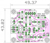
MC-2 single channel Layout... Is it ok😱?
reg
Prasi
Attachments
Last edited:
Guys, I hope you noticed the OP left the building 10 pages, over 100 posts ago, and you are just arguing with each other on something he did not ask for 😉
Just sayin' 😛
Doesnt matter. But the thread is fast becoming a good collection of discrete pre-amps. Love it.
reg
Prasi
I like this one by Juma:
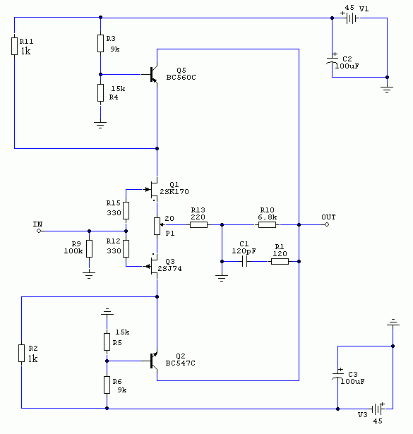
And this:

http://www.diyaudio.com/forums/pass-labs/244106-lsk-pre-baf-2013-a-3.html
Another by Juma:
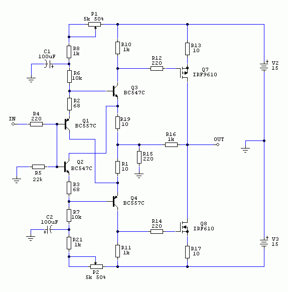
I recently built this Pass F5 allFET headamp which could be a preamp:
http://www.diyaudio.com/forums/atta...27234076-f5-headamp-f5-headamp-schematics.pdf
It is similar to this - just two JFETs and two vertical MOSFETs.
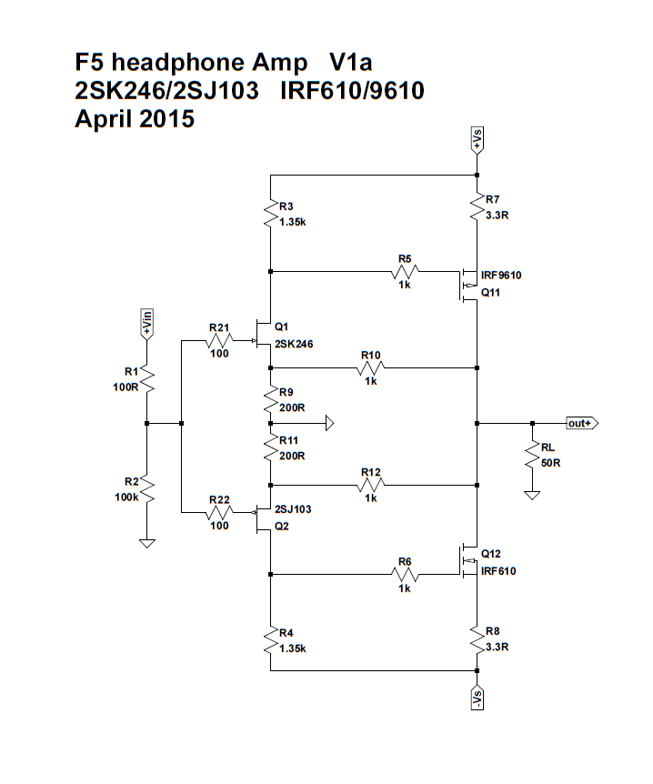
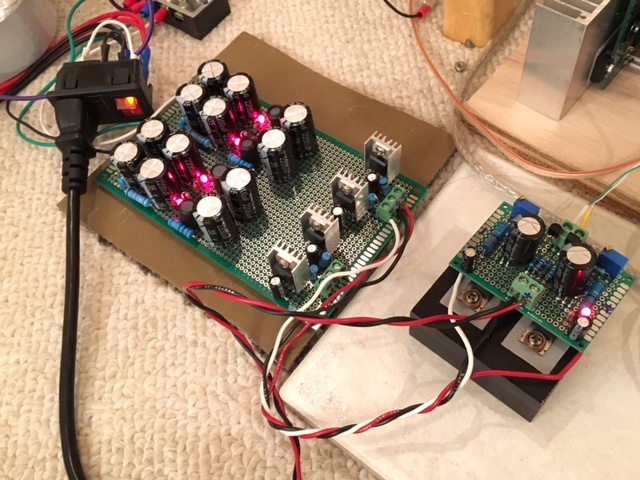
First time I have run a power amp all DC coupled. No caps in signal path. Class A 140mA bias with 15v rail supplies.
Can drive any headphone.
And this:
http://www.diyaudio.com/forums/pass-labs/244106-lsk-pre-baf-2013-a-3.html
Another by Juma:
I recently built this Pass F5 allFET headamp which could be a preamp:
http://www.diyaudio.com/forums/atta...27234076-f5-headamp-f5-headamp-schematics.pdf
It is similar to this - just two JFETs and two vertical MOSFETs.
First time I have run a power amp all DC coupled. No caps in signal path. Class A 140mA bias with 15v rail supplies.
Can drive any headphone.
Last edited:
- Home
- Source & Line
- Analog Line Level
- Transistor Preamp