Thank you for your very appreciated input in the matter, Incidentally I use the DH101 to this very day. Still a very fine sounding piece of equipment boasting bass and treble adjustment.
My version of simple "blameless" pre-amp. Not tested!
Maybe it better to add DC Offset adjustment.
THD at 20kHz should be 0.002978%, sorry.
THD and FFT.
Attachments
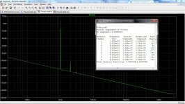
THD and FFT.
Almost done...
Attachments
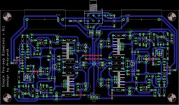
Nice layout bimo!
Will you share the Gerbers after you get everything like you want it?
A give from me 😎
Attachments
I would like to get a Gerber of Ampliwire - looks nice.
I have another idea for a preamp/head amp. I have a bunch of JK VSSA thru hole PCBs. Replace the the outputs (2sk1058/2sj162 latFETs) with IRF610/9610 with a twist of legs 2 and 3 and stand them up with small local heatsinks. Could probably run 24v rails without other modifications.
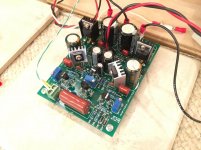
So I made a Jason K VSSA preamp/headamp using IRF610/9610's instead of SK1058/SJ162 latFETs.
I thought I could get away with local heatsinks but they are really hot. Maybe a smaller heatsink can work. I am running 80mA bias and that in itself generates quite a bit of heat.
It's actually able to power my speakers. I might switch out BC550 Vbe multiplier with BD139 mounted to one of the outputs.
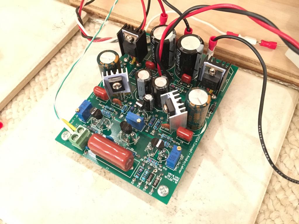
Btw, this exercise shows that with a simple twist of the legs on the IRF610/9610, it can be used in place of the laterals. The bias is very touchy though - so will need temperature feedback Vbe multiplier.
Attachments
Last edited:
I have nothing but a polite "Hello!" for both the cat, and his reproductive system. 😀you may have the wrong cat by the balls.😡
In my opinion, however, this particular circuit is not a cat, but rather, a lame duck. 🙂
Most cats tend to find lame ducks very interesting. But I digress. 😀
The poor performance shown by the LTSpice simulation pretty much ends the discussion. If you know a bit about analogue circuit design, you don't even need an LTSpice simulation to see the problem - it's pretty plain to see from a look at the circuit diagram.
You raised some points worthy of discussion, so let's discuss them a bit:
*) It's a pre-amp; why should it have low output impedance?
The answer is in three parts. First, the performance of the preamp should be dependable, with a reasonable load connected. If the output impedance is extremely high, this requirement cannot be met; open-loop gain, and therefore distortion and bandwidth, vary drastically with the load connected.
Second, a preamp may be called upon to drive a shielded cable. Shielded cables have significant capacitance (typically 30 pF per foot). The cable capacitance creates a low-pass filter with the preamps output impedance. Therefore, in order to ensure that the preamp performs and has adequate bandwidth properly even when connected to a cable of reasonable length, it has to have low output impedance.
Third, shielded cables have imperfect shielding. Some electrical noise and interference will make it through the shield, and arrive at the central conductor, where it will corrupt the audio signal. If the preamp has a low output impedance, it shunts (shorts out) most of this noise; a low preamp output impedance therefore reduces the amount of noise and interference that shows up at the far end of the cable.
These three reasons are so important that every preamp made for professional audio use has a very low output impedance. A hundred ohms or less isn't unusual.
By contrast, the Apex preamp we're discussing actually has an open-loop output impedance of tens of thousands of ohms, or even hundreds of thousands of ohms, depending on output admittance (hoe) of the output devices; when the 3.3k feedback resistor is added, it actually shunts the output, and therefore drops the output impedance to about 3.3k.
Because the raw output impedance is so absurdly high, the loading from the 3.3k feedback resistor is enough to drop the open loop gain considerably. This preamp has such a high output impedance that it actually loses much of its potential performance simply from trying to drive its own negative feedback network!
You can prove this for yourself: grab the LTSpice simulation file I attached to my previous post, load it up in LTSpice, change the 3.3k feedback resistor to 220k, and watch the open loop gain leap from a rather meagre 1200 to a much more reasonable 11,000.
Think about that for a second - this preamp can't even drive its own feedback resistor without suffering drastic performance loss! Does that really seem reasonable to anyone?
*) It is "highly acclaimed as one of the better sounding products by any standard"
Unfortunately, popular acclaim is a very unreliable metric. For example, quite literally, Hitler was popular and highly acclaimed by millions. You can go on You Tube and watch video clips of old film footage showing thousands of people screaming praise and accolades at him.
Since audio electronics is an engineering field, unlike politics, we don't have to rely on popularity to tell us if a design is good or not. Instead, we simulate, build, test, and measure. If the design in question falls on its face at the very first step (simulation), there is no point proceeding further.
As I mentioned earlier, the major problem with this particular preamp implementation is the lack of an output buffer. Unfortunately, that is a major omission, a bit like building a Formula One racing car, and then putting bicycle tyres on it. You may have the high-performance engine and transmission working well, but with those bicycle tyres, you're not going to get much performance out of the car!
-Gnobuddy
The F1 with bicycle tire analogy is a poor one. The preamp in this case is the small electromechanical system that takes the input from the driver's foot pedal position and translates to fuel injection pulses that power the engine. The lack of low impedance drive is of no consequence. The system doesn't even need tires of any kind. The engine and tires are job of the power amp - that's where you want low inpedance drive and damping factor.
You would need a buffer if your amp has some ridiculously low input impedance like a speaker or headphones. However, most power amps fortunately have input impedances in the tens of kohms. With that load, this preamp sounds and works just fine. No buffer needed.
You would need a buffer if your amp has some ridiculously low input impedance like a speaker or headphones. However, most power amps fortunately have input impedances in the tens of kohms. With that load, this preamp sounds and works just fine. No buffer needed.
Last edited:
A give from me 😎
Bimo, many thanks for the PDF files. Good for those who want to etch their own boards.
Can you provide the actual top layer, bottom layer, silkscreen, soldermask and drill Gerber files for those who like to have their boards produced by a board house?
Thanks!
You would need a buffer if your amp has some ridiculously low input impedance like a speaker or headphones. However, most power amps fortunately have input impedances in the tens of kohms. With that load, this preamp sounds and works just fine. No buffer needed.
Analogies aside, apparently you missed the points he made about shielded cables and the problems their capacitance poses.
To make matters worse, some people use really long cables between their line stage/buffer and their power amp.
If the line stage doesn't have a low output impedance along with the balls to send the signal through these longer cables, then that's a problem.
Your statement above would have greater weight if the line stage was directly connected to the input of the power amp without cables.
Any line stage/buffer worth talking about will always have a low output impedance by using either a discrete or a op amp buffer stage before its outputs.
Gnobuddy, this is where subjective departs from objective. The transconductance amp is both faster, and with enough quiescent current, linear enough to be better than most op amp type designs.
I am using a fairly short 0.5m non coaxial cable (unshielded twisted pair) between the preamp and the power amp. I guess you guys are pretty adamant it needs a low impedance driver stage - so sure let's stick one one. What's another transistor anyways? A KSC3503/KSA1381 powered with 35v rails should drive just about any load. I would do that if it didn't work as is. But seeing that it works and sounds fine, I will save my KSA/KSC for another project. I am done talking about this as its getting tiresome.
I still stand by what I said earlier. This is a simple easy to make great sounding preamp. I did not know it was originally designed by the legendary John Curl. Knowing that and hearing how it sounds is worth a lot more than discredit from naysayers who haven't built one.
I still stand by what I said earlier. This is a simple easy to make great sounding preamp. I did not know it was originally designed by the legendary John Curl. Knowing that and hearing how it sounds is worth a lot more than discredit from naysayers who haven't built one.
Last edited:
I still stand by what I said earlier. This is a simple easy to make great sounding preamp. I did not know it was originally designed by the legendary John Curl. Knowing that and hearing how it sounds is worth a lot more than discredit from naysayers who haven't built one.
Hi, X.
You can build my pre-amp and then compare them, like your amplifiers 😉
Amps need followers, but preamps usually don't. However, IF you add a follower, make sure that you add the most linear one possible. Usually this is a complementary push-pull Class A stage, either fet or bipolar. Run as high a quiescent current as is practical. This will separate your design from a typical IC.
Bimo, Sure - did you post Gerbers yet? Yours looks too complicated for veroboard.
Perhaps he will. That's why I asked him a few posts back.
He's already posted PDFs for people who want to etch their own boards.
I would also like to try his design.
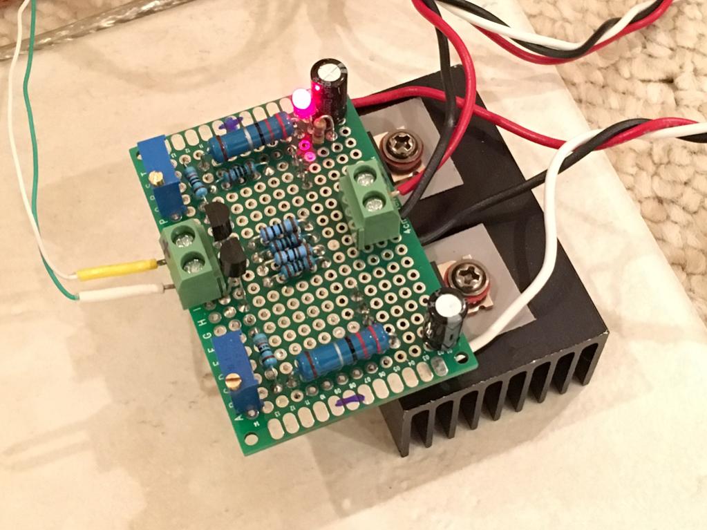
I just made the F5 headamp last night. It's class A complementary - can probably work as a preamp as well? It has only 2 stages but second stage is power stage.
http://www.diyaudio.com/forums/pass-labs/271926-f5-headamp.html#post4270427
http://www.diyaudio.com/forums/pass-labs/271926-f5-headamp.html#post4270427
Perhaps he will. That's why I asked him a few posts back.
He's already posted PDFs for people who want to etch their own boards.
I would also like to try his design.
My files on my home's computer. I will at home on Saturday and Sunday.
This will separate your design from a typical IC.
Sounds like you may have a dislike for or grudge against ICs. I can sort of understand that being you've designed discrete circuits most of your career.
Still the fact remains that a very good sounding line stage can be built with only a couple of op amps and a few resistors. Walter Jung proved that years ago.
No doubt one can get higher current out of a discrete output stage, but this usually isn't required except for very long cable runs or other problematic loads.
I just made the F5 headamp last night. It's class A complementary - can probably work as a preamp as well? It has only 2 stages but second stage is power stage.
Yes, you should be able to use it as a preamp.
Just curious...are you using original Toshiba JFETs or Ali specials?
- Home
- Source & Line
- Analog Line Level
- Transistor Preamp