@ufudu:
the numbers with your model are incredibly low:
pentode @150/150/-1v --> plate=4ma; screen=0.1ma
triode @150/-1v --> plate=3ma
this is just 1/3 of data sheet:
pentode @150/150/-1v --> plate=13ma; screen<=2ma
triode @150/-1v --> plate=8ma
either your tubes are completely worn or some scaling problem ...
are you shure KVB should be zero in your model ? (says kvb .0) ?
I also find these tubes oscillate whenever given the slightest opportunity ...
I measure this:
pentode @150/150/-1v --> plate=18ma; screen=1.7ma
triode @150/-1v --> plate=8ma
pentodes are all on the high side, triodes spot on;
my specimen are production code 9201 and 9111, so very late ...
would be interesting to see models promised by @mogliaa
currently I use these models as attached.
Attachments
I also find these tubes oscillate whenever given the slightest opportunity ...
Hey, thanks for the additional models. jackinnj also contributed a model, which agrees fairly closely with the ones you're using.
In the real world, how much work have you had to do to keep these tubes from oscillating? Was it enough to use grid stoppers and keep wires short and tidy? Or did you have to resort to ferrite beads and other extreme measures?
...would be interesting to see models promised by @mogliaa
Yes, those and the generic directly heated triode model he uses, so I can try out his 4P1L model as well. He's put a lot of work into it, but I'm so far behind the curve, I can't seem to get his models to work.
--
@ufudu:
the numbers with your model are incredibly low:
either your tubes are completely worn or some scaling problem ..
Yes, we concluded that the tubes measured too low to be "useful"...
No, it was not a scaling problem, I rechecked the measurements with my "reference" triode & pentode.
I did consider a possible oscillation problem and did the standard thing to reduce this in the uTracer, but it made no difference..
Anyway, now you have a model for a "worn out" tube to pop into the simulation 🙂
Do someone has a 6J51P penthode model?
thanks.
kees
6J51P is supposed to be equivalent of American 6EJ7 and European EF184. I have the Ayumi models.
PENTODE:
Code:
*
* Generic pentode model: 6EJ7
* LTspiceIV
* Copyright 2003--2008 by Ayumi Nakabayashi, All rights reserved.
* Version 3.10, Generated on Sat Mar  8 22:39:53 2008
*            Plate
*            | Screen Grid
*            | |  Control Grid
*            | |  |  Cathode
*            | |  |  |
.SUBCKT 6EJ7 A G2 G1 K
BGG   GG   0 V=V(G1,K)+0.40321166
BM1   M1   0 V=(0.0054275937*(URAMP(V(G2,K))+1e-10))**-0.61801526
BM2   M2   0 V=(0.7082102*(URAMP(V(GG)+URAMP(V(G2,K))/53.760436)))**2.1180153
BP    P    0 V=0.019963362*(URAMP(V(GG)+URAMP(V(G2,K))/75.910283))**1.5
BIK   IK   0 V=U(V(GG))*V(P)+(1-U(V(GG)))*0.011540933*V(M1)*V(M2)
BIG   IG   0 V=0.0099816812*URAMP(V(G1,K))**1.5*(URAMP(V(G1,K))/(URAMP(V(A,K))+URAMP(V(G1,K)))*1.2+0.4)
BIK2  IK2  0 V=V(IK,IG)*(1-0.4*(EXP(-URAMP(V(A,K))/URAMP(V(G2,K))*15)-EXP(-15)))
BIG2T IG2T 0 V=V(IK2)*(0.71666698*(1-URAMP(V(A,K))/(URAMP(V(A,K))+10))**1.5+0.28333302)
BIK3  IK3  0 V=V(IK2)*(URAMP(V(A,K))+5500)/(URAMP(V(G2,K))+5500)
BIK4  IK4  0 V=V(IK3)-URAMP(V(IK3)-(0.010377457*(URAMP(V(A,K))+URAMP(URAMP(V(G2,K))-URAMP(V(A,K))))**1.5))
BIP   IP   0 V=URAMP(V(IK4,IG2T)-URAMP(V(IK4,IG2T)-(0.010377457*URAMP(V(A,K))**1.5)))
BIAK  A    K I=V(IP)+1e-10*V(A,K)
BIG2  G2   K I=URAMP(V(IK4,IP))
BIGK  G1   K I=V(IG)
* CAPS
CGA   G1  A  0.005p
CGK   G1  K  6p
C12   G1  G2 4p
CAK   A   K  3p
.ENDS
TRIODE:
Code:
*
* Generic triode model: 6EJ7T
* LTspiceIV
* Copyright 2003--2008 by Ayumi Nakabayashi, All rights reserved.
* Version 3.10, Generated on Sat Mar  8 22:39:53 2008
*             Plate
*             | Grid
*             | | Cathode
*             | | |
.SUBCKT 6EJ7T A G K
BGG   GG   0 V=V(G,K)+0.40321166
BM1   M1   0 V=(0.0054275937*(URAMP(V(A,K))+1e-10))**-0.61801526
BM2   M2   0 V=(0.7082102*(URAMP(V(GG)+URAMP(V(A,K))/53.760436)+1e-10))**2.1180153
BP    P    0 V=0.019963362*(URAMP(V(GG)+URAMP(V(A,K))/75.910283)+1e-10)**1.5
BIK   IK   0 V=U(V(GG))*V(P)+(1-U(V(GG)))*0.011540933*V(M1)*V(M2)
BIG   IG   0 V=0.0099816812*URAMP(V(G,K))**1.5*(URAMP(V(G,K))/(URAMP(V(A,K))+URAMP(V(G,K)))*1.2+0.4)
BIAK  A    K I=URAMP(V(IK,IG)-URAMP(V(IK,IG)-(0.010377457*URAMP(V(A,K))**1.5)))+1e-10*V(A,K)
BIGK  G    K I=V(IG)
* CAPS
CGA   G    A 4p
CGK   G    K 6p
CAK   A    K 3p
.ENDS
--
Last edited:
Having trouble with Ayumi models. I "converted" his 12AT7 inc. model to Pspice so perhaps I made an error. I've checked it a number of times and now need another opinion please. Pspice crashes on a "can't converge" error.
Thanks.
The lines commented out with * are the ones causing the sim to crash.
Thanks.
The lines commented out with * are the ones causing the sim to crash.
Code:
* Generic triode model: 12AT7
* Copyright 2003--2008 by Ayumi Nakabayashi, All rights reserved.
* Version 3.10, Generated on Sat Mar  8 22:41:07 2008
*             Plate
*             | Grid
*             | | Cathode
*             | | |
.SUBCKT 12AT7 A G K
BGG   GG   0 V=V(G,K)+0.67585931
BM1   M1   0 V=(0.015420581*(URAMP(V(A,K))+1e-10))^-1.768756
BM2   M2   0 V=(0.45889017*(URAMP(V(GG)+URAMP(V(A,K))/35.090106)+1e-10))^3.268756
BP    P    0 V=0.0031809222*(URAMP(V(GG)+URAMP(V(A,K))/76.46733)+1e-10)^1.5
BIK   IK   0 V=U(V(GG))*V(P)+(1-U(V(GG)))*0.0042575005*V(M1)*V(M2)
BIG   IG   0 V=0.0015904611*URAMP(V(G,K))^1.5*(URAMP(V(G,K))/(URAMP(V(A,K))+URAMP(V(G,K)))*1.2+0.4)
BIAK  A    K I=URAMP(V(IK,IG)-URAMP(V(IK,IG)-(0.0016530623*URAMP(V(A,K))^1.5)))+1e-10*V(A,K)
BIGK  G    K I=V(IG)
* CAPS
CGA   G    A 1.5p
CGK   G    K 2.2p
CAK   A    K 0.5p
.ENDS
Code:
* Generic triode model: 12AT7
* Copyright 2003--2008 by Ayumi Nakabayashi, All rights reserved.
* Version 3.10, Generated on Sat Mar  8 22:41:07 2008
*             Plate
*             | Grid
*             | | Cathode
*             | | |
.SUBCKT 12AT7 A G K
EGG   GG   0 VALUE={V(G,K)+0.67585931}
*EM1   M1   0 VALUE={(0.015420581*(MAX(0,(V(A,K)))+1e-10))^-1.768756}
EM2   M2   0 VALUE={(0.45889017*(MAX(0,(V(GG))+MAX(0,(V(A,K)))/35.090106)+1e-10))^3.268756}
EP    P    0 VALUE={0.0031809222*(MAX(0,(V(GG))+MAX(0,(V(A,K)))/76.46733)+1e-10)^1.5}
*EIK   IK   0 VALUE={STP(V(GG))*V(P)+(1-STP(V(GG)))*0.0042575005*V(M1)*V(M2)}
EIG   IG   0 VALUE={0.0015904611*MAX(0,(V(G,K)))^1.5*(MAX(0,(V(G,K)))/(MAX(0,(V(A,K)))+MAX(0,(V(G,K))))*1.2+0.4)}
*GIAK  A    K VALUE={MAX(0,(V(IK,IG))-MAX(0,(V(IK,IG))-(0.0016530623*MAX(0,(V(A,K)))^1.5))+1e-10*V(A,K))}
GIGK  G    K VALUE={V(IG)}
* CAPS
CGA   G    A 1.5p
CGK   G    K 2.2p
CAK   A    K 0.5p
.ENDS
Last edited:
I should mention that the Ayumi models seem to sim ok when in a circuit. It is only when I am trying to perform a DC sweep of them that they crash. The 12AY7 model works, but 12AX7, 12AU7, and 12AT7 crash. The M1 voltage goes to 10GV.
Model runs fine in LTspice in both AC and DC sweep/analysis. However in Micro-Cap it throws an overflow/floating point out of range error unless I change in line EM1 '+e-10' to '+e-03'.
Try these two models, as they run in Micro-Cap without any errors.
This one runs a little slow in Micro-Cap. I get incorrect results in AC analysis when I make the change in the EM1 line, but DC sweep/analysis is ok.
Try these two models, as they run in Micro-Cap without any errors.
Code:
*
* Generic triode model: 12AT7
* Copyright 2003--2008 by Ayumi Nakabayashi, All rights reserved.
* Version 3.10, Generated on Sat Mar  8 22:41:07 2008
*                 Plate
*                 | Grid
*                 | | Cathode
*                 | | |
.SUBCKT 12AT7_ANP A G K
EGG   GG   0 VALUE={V(G,K)+0.67585931}
EM1   M1   0 VALUE={(0.015420581*(MAX(0,(V(A,K)))+1e-03))^-1.768756}
EM2   M2   0 VALUE={(0.45889017*(MAX(0,(V(GG))+MAX(0,(V(A,K)))/35.090106)+1e-10))^3.268756}
EP    P    0 VALUE={0.0031809222*(MAX(0,(V(GG))+MAX(0,(V(A,K)))/76.46733)+1e-10)^1.5}
EIK   IK   0 VALUE={STP(V(GG))*V(P)+(1-STP(V(GG)))*0.0042575005*V(M1)*V(M2)}
EIG   IG   0 VALUE={0.0015904611*MAX(0,(V(G,K)))^1.5*(MAX(0,(V(G,K)))/(MAX(0,(V(A,K)))+MAX(0,(V(G,K))))*1.2+0.4)}
GIAK  A    K VALUE={MAX(0,(V(IK,IG))-MAX(0,(V(IK,IG))-(0.0016530623*MAX(0,(V(A,K)))^1.5))+1e-10*V(A,K))}
GIGK  G    K VALUE={V(IG)}
* CAPS
CGA   G    A 1.5p
CGK   G    K 2.2p
CAK   A    K 0.5p
.ENDS
Code:
*
* Generic triode model: 12AT7
* Copyright 2003--2008 by Ayumi Nakabayashi, All rights reserved.
* Version 3.10, Generated on Sat Mar  8 22:41:07 2008
*             Plate
*             | Grid
*             | | Cathode
*             | | |
.SUBCKT 12AT7 A G K
EGG   GG   0 VALUE={V(G,K)+0.67585931}
EM1   M1   0 VALUE={(0.015420581*(LIMIT(V(A,K),0,1e16)+1e-10))^-1.768756}
EM2   M2   0 VALUE={(0.45889017*(LIMIT((V(GG)+LIMIT(V(A,K),0,1e16)/35.090106),0,1e16)+1e-10))^3.268756}
EP    P    0 VALUE={0.0031809222*(LIMIT((V(GG)+LIMIT(V(A,K),0,1e16)/76.46733),0,1e16)+1e-10)^1.5}
EIK   IK   0 VALUE={STP(V(GG))*V(P)+(1-STP(V(GG)))*0.0042575005*V(M1)*V(M2)}
EIG   IG   0 VALUE={0.0015904611*LIMIT(V(G,K),0,1e16)^1.5*(LIMIT(V(G,K),0,1e16)/(LIMIT(V(A,K),0,1e16)+LIMIT(V(G,K),0,1e16))*1.2+0.4)}
GIAK  A    K VALUE={LIMIT(V(IK,IG)-LIMIT(V(IK,IG)-(0.0016530623*LIMIT(V(A,K),0,1e16)^1.5),0,1e16),0,1e16)+1e-10*V(A,K)}
GIGK  G    K VALUE={V(IG)}
* CAPS
CGA   G    A 1.5p
CGK   G    K 2.2p
CAK   A    K 0.5p
.ENDSThanks Wayne, I will give them a try. It is odd that the 12AY7 and 12AX7 Ayumi models work (last post was incorrect in stating that 12AX7 didn't work), yet the others don't.
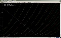
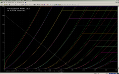
In case anyone is interested, here is a comparison of Ayumi's vs. Rydel's (created by Wayne using Curvecaptor) plate curves for the 12AX7. First is direct comparison between the two, then with the actual curves taken from the GE datasheet.
Ayumi's Vg=0V trace goes a little off.
Next I'm going to compare the Ig models from Ayumi and Rydel.
Attachments
Last edited:
I changed that value to"1e-3" as you suggested and it works. The LIMIT did not work.
I don't think this affects the results much, if any.
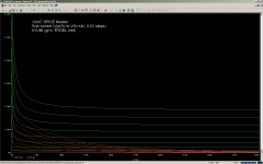
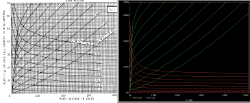
For those that may be interested, here is a comparison of Ayumi's 12AT7 model with the GE data sheet (sorry I don't have ripped data yet), in the overdrive regime (Vg=0V to Vg=+8V).
The plate curves don't appear to be terribly accurate. The grid current is quite a bit off. A good starting point perhaps.
I don't think this affects the results much, if any.
For those that may be interested, here is a comparison of Ayumi's 12AT7 model with the GE data sheet (sorry I don't have ripped data yet), in the overdrive regime (Vg=0V to Vg=+8V).
The plate curves don't appear to be terribly accurate. The grid current is quite a bit off. A good starting point perhaps.
Attachments
Having trouble with Ayumi models. I "converted" his 12AT7 inc. model to Pspice so perhaps I made an error. I've checked it a number of times and now need another opinion please. Pspice crashes on a "can't converge" error.
<snip>
i know that for ltspice i had to change the ^ in to **
Last edited:
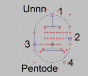
Do SPICEy pentodes really have 4 pins?
I tried to go through the (as of today) 122 pages of http://www.diyaudio.com/forums/tubes-valves/243950-vacuum-tube-spice-models.html for a model of an EL91. I've come across the Koren model, but I want to make sure that I'm not making a gross error. Most pentode SPICE models have 4 connections, rather than 5. So In LTSpice, it would look like this:-
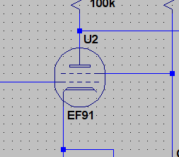
It works in a simulation, but why do we not just use the proper pentode schematic image that comes supplied? I know that typically a grid is shorted out, but that seems like confusing the details. Is this one of my fundamental misunderstandings again 😕 ?
PS. Are there any alternative (better) models than Koren? Ayumi doesn't have it.
I tried to go through the (as of today) 122 pages of http://www.diyaudio.com/forums/tubes-valves/243950-vacuum-tube-spice-models.html for a model of an EL91. I've come across the Koren model, but I want to make sure that I'm not making a gross error. Most pentode SPICE models have 4 connections, rather than 5. So In LTSpice, it would look like this:-
It works in a simulation, but why do we not just use the proper pentode schematic image that comes supplied? I know that typically a grid is shorted out, but that seems like confusing the details. Is this one of my fundamental misunderstandings again 😕 ?
PS. Are there any alternative (better) models than Koren? Ayumi doesn't have it.
Attachments

Because the supressor grid is assumed connected to the cathode, the most usual way of doing it.
'Spice' is a virtual world and is not that accurate so to have a Pentode drawn as a Tetrode is not unusual.
The Tetrode : Electron Tubes - Electronics Textbook
The Tetrode : Electron Tubes - Electronics Textbook
.SUBCKT EF91 1 2 3 4 ; A G2 G1 C (Pentode)
Open Pentode.asy file edit the pin number as above (and attached) and save as say Pentode3.asy, it should work. Each time you run into similar problem always check first if pin is mismatched with model. Paint a new model if you want, using model paint tool from Model Paint Tools: Trace Tube Parameters over Plate Curves, Interactively
Some datasheets do not show screen current so you cannot sim correctly for the screen parameter with model painted as such. EF91 is same as 6AM6.
Attachments
Here is the step by step procedure to create SPICE models for the triode, the 12AU7 tube is used as an example below:
1. Save the data points in CSV format with three columns: Eg, Ep, Ip, please note that more data points do not necessarily increase the model's accuracy;
2. Launch R, and change the working directory to where the pctube.r file is stored on your PC - File -> Change dir...;
3. In R, load pctube.r - File -> Source R code..., select pctube.r;
4. At the R command prompt, type: Ip.cal("12AU7.csv", "t12AU7", Cgp=1.5e-12, Ci=1.6e-12, Co=0.4e-12), with the capacitance values taken from the datasheet;
5. Ip.cal will generate a curve fitted Ep-Ip characteristic graph on the screen, check for any obvious error (usually due to bad data entries);
6. At the R command prompt, type r2spice(t12AU7, "12AU7", "12AU7", Cgp=1.5e-12, Ci=1.6e-12, Co=0.4e-12), this will generate three varieties of SPICE models - PSPICE, SIMetrix and TINA. The models can be found in your work directory.
Bada bing, bada boom... you got your models.
I decided to give this a try, and I had some success. At least with the 12AU7 example.
I had a look through Ayumi's R file using Notepad++ and I see he has many "objects" (read in the R program) in the code, including some code for each tube model in his pctube archive. There are many more functions in there than just IP curves.
Does this mean only the tube models that are in his code can be modeled? If not, then how does one tell the script that the model is for a triode, pentode, or diode?
Would it be possible to find the optimization code and add the exponent for the plate voltage (1.5) into the optimization? I think this would produce a more accurate model. See below for the statement I'm referring to:
Code:
EP P 0 VALUE={0.00087237591*(MAX(0,(V(GG))+MAX(0,(V(A,K)))/21.021735)+1e-10)^[B]1.5[/B]}No, any tube can be modeled if the appropriate Ep/Ip curves are supplied. All three types of tube can be modeled, the R commands for each are shown on Ayumi's web page.Does this mean only the tube models that are in his code can be modeled? If not, then how does one tell the script that the model is for a triode, pentode, or diode?
I believe that is already done, but bear in mind that 1.5 is not going to provide the best fit for all the tubes, so there are bound to be deviations between some of the models and their datasheets. On the whole, with some rare exceptions, I found the Ayumi models are sufficient for simulation purposes, i.e., the results are within the tubes' manufacturing tolerances.Would it be possible to find the optimization code and add the exponent for the plate voltage (1.5) into the optimization? I think this would produce a more accurate model.
Could you help by quick example in showing how? Much Appreciated 🙂No, any tube can be modeled if the appropriate Ep/Ip curves are supplied. All three types of tube can be modeled, the R commands for each are shown on Ayumi's web page.
No, every model that Ayumi has produced uses 1.5 for that exponent, so I can't see how it would figure into the optimization.I believe that is already done, but bear in mind that 1.5 is not going to provide the best fit for all the tubes, so there are bound to be deviations between some of the models and their datasheets. On the whole, with some rare exceptions, I found the Ayumi models are sufficient for simulation purposes, i.e., the results are within the tubes' manufacturing tolerances.
- Home
- Amplifiers
- Tubes / Valves
- Vacuum Tube SPICE Models