I've gone through Ayumi's pages but can't find how to implement his R code to produce other models such as pentodes, diodes, and transformers etc.
Any help would be appreciated.
Any help would be appreciated.
It's been awhile since I looked at Ayumi's website, there does not seem to be a command for the diode model, but here is the translation for the pentode model:
"For pentodes, additional parameters need to be included in pentode.chara, which should include the plate voltage, the screen voltage, the grid voltage, the plate current, the screen grid current and the internal resistance, e.g., for 6L6, Ep = 250 V, Eg2 = 250 V, Eg = -14 V, Ip = 72 mA, Ig2 = 5 mA, rp = 22.5 kΩ and could be written as:
> Ip.cal ("6L6.csv", "t6L6T", Cgp=0.6e-12, Ci=10e-12, Co=6.5e-12, pentode.chara=c(250, 250, -14, 72e-3, 5e-3, 22.5e3), ig=c(10, 18e-3, 32e-3))"
Please remember that you need to provide the triode-connected Ep-Ip characteristic data to generate the pentode model, not the pentode Ep-Ip characteristic.
Yes, Ayumi uses the ideal triode exponent 1.5 for the optimization routine, I suppose you can modify the code but bear in mind that the tube models and the pctube program are copyrighted by Ayumi, so you must contact him for permission to alter the code.
I would add that the exponent in the following statement is also always 1.5:
Code:
GIAK A K VALUE={MAX(0,(V(IK,IG))-MAX(0,(V(IK,IG))-(0.0016530623*MAX(0,(V(A,K)))^[B]1.5[/B]))+1e-10*V(A,K))}I have been playing with the models using his as a starting point. I won't be changing his code as I would not know where that specific part is nor what to do with it. 😉
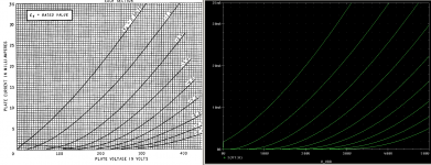
I've got a final version for the 12AT7 that I like and that seems to match pretty close to the GE datasheet. Grid current model is an exponent-modified version from Rydel/Excem as it fits better and is easier to tweak by hand than Ayumi's.
See next post.
I've got a final version for the 12AT7 that I like and that seems to match pretty close to the GE datasheet. Grid current model is an exponent-modified version from Rydel/Excem as it fits better and is easier to tweak by hand than Ayumi's.
See next post.
Here's my 12AT7(AY) using Ayumi's model as a base. Removed and tweaked statements are present but commented out. Tweaked Rydel Ig model added in the "Gg" statement.
Code:
.SUBCKT 12AT7AY A G K
EGG   GG   0 VALUE={V(G,K)+0.67585931}
EM1   M1   0 VALUE={(0.015420581*(MAX(0,(V(A,K))+1e-3)))^-1.768756}
EM2   M2   0 VALUE={(0.45889017*(MAX(0,(V(GG))+MAX(0,(V(A,K)))/35.090106)+1e-10))^3.268756}
EP    P    0 VALUE={0.0031809222*(MAX(0,(V(GG))+MAX(0,(V(A,K)))/76.46733)+1e-10)^1.54}
EIK   IK   0 VALUE={STP(V(GG))*V(P)+(1-STP(V(GG)))*0.0042575005*V(M1)*V(M2)}
EIG   IG   0 VALUE={0.0026*MAX(0,(V(G,K)))^1.53*(MAX(0,(V(G,K)))/(MAX(0,(V(A,K)))+MAX(0,(V(G,K))))*1.1+.5)}
*EIG   IG   0 VALUE={0.0015904611*MAX(0,(V(G,K)))^1.5*(MAX(0,(V(G,K)))/(MAX(0,(V(A,K)))+MAX(0,(V(G,K))))*1.2+.4)}
GIAK  A    K VALUE={MAX(0,(V(IK,IG))-MAX(0,(V(IK,IG))-(0.0016530623*MAX(0,(V(A,K)))^1.5))+1e-10*V(A,K))}
*GIGK  G    K VALUE={V(IG)}
Gg G K VALUE={IF(V(G,K)>0, 1.3m * ((( 28.2 +V(A,K))/( 20.2 +V(A,K)))**3)*V(G,K)**1.6,0)}
* CAPS
CGA   G    A 1.5p
CGK   G    K 2.2p
CAK   A    K 0.5p
.ENDS
Attachments
mmm...Here's my 12AT7(AY) using Ayumi's model as a base. Removed and tweaked statements are present but commented out. Tweaked Rydel Ig model added in the "Gg" statement.
check if this model can actually work in a simple common cathode gain stage, there must be some typo somewhere
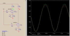
Here is one test. Compared with a RYDEL 5-parameter model. The AYUMI model does not match so well at higher plate voltages, which is why the positive side is higher in amplitude than the RYDEL model. Vsig=2Vp.
What were you having problems with?
What were you having problems with?
Attachments
Last edited:
I don t know what software are You running, but for sure the model does not work with LTSpiceWhat were you having problems with?
The Ayumi model works like a charm
The one You posted (#1225) does not work at all
* Generic triode model: 12AT7
* Copyright 2003--2008 by Ayumi Nakabayashi, All rights reserved.
* Version 3.10, Generated on Sat Mar 8 22:41:07 2008
* Plate
* | Grid
* | | Cathode
* | | |
.SUBCKT 12AT7 A G K
BGG GG 0 V=V(G,K)+0.67585931
BM1 M1 0 V=(0.015420581*(URAMP(V(A,K))+1e-10))**-1.768756
BM2 M2 0 V=(0.45889017*(URAMP(V(GG)+URAMP(V(A,K))/35.090106)+1e-10))**3.268756
BP P 0 V=0.0031809222*(URAMP(V(GG)+URAMP(V(A,K))/76.46733)+1e-10)**1.5
BIK IK 0 V=U(V(GG))*V(P)+(1-U(V(GG)))*0.0042575005*V(M1)*V(M2)
BIG IG 0 V=0.0015904611*URAMP(V(G,K))**1.5*(URAMP(V(G,K))/(URAMP(V(A,K))+URAMP(V(G,K)))*1.2+0.4)
BIAK A K I=URAMP(V(IK,IG)-URAMP(V(IK,IG)-(0.0016530623*URAMP(V(A,K))**1.5)))+1e-10*V(A,K)
BIGK G K I=V(IG)
* CAPS
CGA G A 1.5p
CGK G K 2.2p
To use that model in LTspice, you need to change all instances of ^ to **.I don t know what software are You running, but for sure the model does not work with LTSpice
The Ayumi model works like a charm
The one You posted (#1225) does not work at all
I must have developed an advanced case of blindness, I would have sworn that all "**" were in place. Sincere apologies to poynt99To use that model in LTspice, you need to change all instances of ^ to **.
cheers
J.
I'm using OrCad PSpice.I don t know what software are You running, but for sure the model does not work with LTSpice
The Ayumi model works like a charm
The one You posted (#1225) does not work at all
*
* Generic triode model: 12AT7
* Copyright 2003--2008 by Ayumi Nakabayashi, All rights reserved.
* Version 3.10, Generated on Sat Mar 8 22:41:07 2008
* Plate
* | Grid
* | | Cathode
* | | |
.SUBCKT 12AT7 A G K
BGG GG 0 V=V(G,K)+0.67585931
BM1 M1 0 V=(0.015420581*(URAMP(V(A,K))+1e-10))**-1.768756
BM2 M2 0 V=(0.45889017*(URAMP(V(GG)+URAMP(V(A,K))/35.090106)+1e-10))**3.268756
BP P 0 V=0.0031809222*(URAMP(V(GG)+URAMP(V(A,K))/76.46733)+1e-10)**1.5
BIK IK 0 V=U(V(GG))*V(P)+(1-U(V(GG)))*0.0042575005*V(M1)*V(M2)
BIG IG 0 V=0.0015904611*URAMP(V(G,K))**1.5*(URAMP(V(G,K))/(URAMP(V(A,K))+URAMP(V(G,K)))*1.2+0.4)
BIAK A K I=URAMP(V(IK,IG)-URAMP(V(IK,IG)-(0.0016530623*URAMP(V(A,K))**1.5)))+1e-10*V(A,K)
BIGK G K I=V(IG)
* CAPS
CGA G A 1.5p
CGK G K 2.2p
So for LT Spice You would have to convert all the MAX statements to URAMP, and apparently all the ^ to **. I guess you did one, but not the other. 😉 Does it work now?
You may also have to change the "STP" statement.
Last edited:
"Does it work now?
"**" in place of "^", the model works
"URAMP" in place of "MAX", does not work again
still trying, I will report if I succeed...
Try this. I took Ayumi's original model and tweaked a few parameters. I didn't add Rydel's grid current model, as my tweak to the parameters of Ayumi's grid model is pretty close.
My changes are in bold.
My changes/additions are in bold.
My changes are in bold.
Code:
*
* Based on model by Ayumi Nakabayashi.
* 2016-09-13 by poynt99.
*             Plate
*             | Grid
*             | | Cathode
*             | | |
.SUBCKT 12AT7 A G K
BGG   GG   0 V=V(G,K)+0.67585931
BM1   M1   0 V=(0.015420581*(URAMP(V(A,K))+1e-10))**-1.768756
BM2   M2   0 V=(0.45889017*(URAMP(V(GG)+URAMP(V(A,K))/35.090106)+1e-10))**3.268756
BP    P    0 V=0.0031809222*(URAMP(V(GG)+URAMP(V(A,K))/76.46733)+1e-10)[B]**1.54[/B]
BIK   IK   0 V=U(V(GG))*V(P)+(1-U(V(GG)))*0.0042575005*V(M1)*V(M2)
BIG   IG   0 V=[B]0.0026[/B]*URAMP(V(G,K))[B]**1.53[/B]*(URAMP(V(G,K))/(URAMP(V(A,K))+URAMP(V(G,K)))*[B]1.1+0.5[/B])
BIAK  A    K I=URAMP(V(IK,IG)-URAMP(V(IK,IG)-(0.0016530623*URAMP(V(A,K))**1.5)))+1e-10*V(A,K)
BIGK  G    K I=V(IG)
* CAPS
CGA   G    A 1.5p
CGK   G    K 2.2p
CAK   A    K 0.5p
.ENDS
Last edited by a moderator:
 Please remove the copyright information if and when you make any change to the original model.
I've only changed some of the parameters, otherwise the model is still his, and generated by his algorithm/program.
It would be no different than using his algorithm with data I traced from my own datasheet that would obviously generate a slightly different model than his published one.
But I'm no expert on copyright. If I was him, I would still want the copyright there as in my opinion the model is still his.
It would be no different than using his algorithm with data I traced from my own datasheet that would obviously generate a slightly different model than his published one.
But I'm no expert on copyright. If I was him, I would still want the copyright there as in my opinion the model is still his.
But I'm no expert on copyright. If I was him, I would still want the copyright there as in my opinion the model is still his.
I think copyright law would specify what to do here, if it were me I would mention the model was based on his model, but not credit him with my changes after all I may be an idiot.
@ponyt99 - his program isn't copyrighted AFAIK, but the specific models that he produced using the program are, so if you modify them in any way, they are no longer Ayumi models, I hope the distinction is clear.
Hi again
model in post #1233 works Ok, but I can not see any difference against the original, when used in a simple circuit.
Maybe if you plot anode curves there are, I dont know
model in post #1233 works Ok, but I can not see any difference against the original, when used in a simple circuit.
Maybe if you plot anode curves there are, I dont know
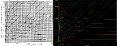
Yes, you should notice a slight change in the plate curves due to the exponent change for the plate current (1.54 from 1.50).
The biggest change is for the grid current, but you won't see that unless you run the grid current curves or you overdrive the amplifier stage. The grid current is much higher so for Vgk values greater than 0V, Ig will increase at a faster rate than the original. In real applications, this means grid limiting will be more flat or abrupt.
The biggest change is for the grid current, but you won't see that unless you run the grid current curves or you overdrive the amplifier stage. The grid current is much higher so for Vgk values greater than 0V, Ig will increase at a faster rate than the original. In real applications, this means grid limiting will be more flat or abrupt.
- Home
- Amplifiers
- Tubes / Valves
- Vacuum Tube SPICE Models