Dating back from March 2011 and initiated by George Boudreau, the SDR-Widget is an interface based on the Atmel AT32UC3A3 microcontroller aiming at providing high quality audio using the USB Audio Class standard (UAC1 and UAC2).Yesterday I found what I was looking for to be confident in being able to develop the Async USB with explicit feedback, which was my main concern. It derives from the the Audio-widget project that's here : http://www.diyaudio.com/forums/digital-source/185761-open-source-usb-interface-audio-widget-10.html
Now please read post #99 here audio-widget-10.html, where tdtsai from C-Media Inc. offers to develop a driver for Windows. What's the current status in August 2016 ?
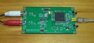
The Audio Widget designed by George Boudreau relies on a ES9023 Stereo DAC, a SiLabs Si532 dual rate oscillator as a DAC clock, and a 144 pin AT32UC3A3256 CPU. See the attached .jpg.
The code running in the Atmel AT32UC3A3 is documented on github, here : https://github.com/borgestrand/sdr-widget/tree/master/src
Latest commit 928d195 is dating back from 20 Oct 2012.
There is another Audio Widget, this time designed by PAVOUK, see the attached .pdf and webpage http://www.pavouk.org/hw/audiosystem20/en_at32uc3a3256usbi2s.html
It reads : For Linux and Mac are not needed any drivers for full use of module, because they are part of system core. Windows includes only support for UAC1 mode and for full use is needed to download drivers from original pages. It is needed to get right driver which will know exact card ID according to used firmware. In Linux I hit the troubles that in Alsa mode doesn't work playing in XMMS application. When I use OSS emulation that it works perfectly in UAC2 mode. In other players I didn't see this problem and with another USB-I2S converter XMMS works correctly. In UAC1 mode is situation a little worse. In OSS mode it plays incorrectly. Music jumps and tears. I can't tell if problem is in firmware, in player or in a kernel driver.
The schematic remains simple and qualitative :
- two quartz oscillators supposedly acting as Master Audio Clock (USB Async Audio ?),
- a flip-flop dividing the 512 x Fs frequency by two for guaranteeing a perfect 50% duty cycle on the 256 x Fs
- a galvanically isolated I2S + MCLK bus, thanks to a ISO7240 chip receiving an external 3.3 Volt power supply.
The most useful document I found about UAC1 working async, and UAC2 working async, can be found on the Henry Audio USB DAC 128 mkII description, dating back from October 2014. Including the schematic.
Grab it here : http://www.henryaudio.com/uploads/fact_sheet_mkII.pdf
I'm not insisting on the schematic, because it is more complicated than the PAVOUK one. Please try understanding the PAVOUK schematic, and you'll be fine with your STM32F7 implementation. Add a frequency divider (D-type flip-flops) for generating at will, 256 x Fs (SAI in I2S protocol), and 64 x Fs (SAI in SPDIFTX protocol).
Anyway, the Henry Audio USB DAC 128 mkII description says :
USB Audio Class 1 & 2
USB Audio has two different ways to work, USB Audio Class 1 and 2. The USB DAC 128 mkII will operate in both UAC1 and UAC2. The reason for supporting two modes is that only UAC1 is supported natively in Windows while UAC2 is needed for high resolution playback. When the DAC is first powered on it will use UAC1. That way it will work right out of the box on all computers, and the playback will have more than CD quality. OS X, Linux, iOS and Android support both UAC1 and UAC2 natively. On those systems you may as well select UAC2 as you start using your new DAC. For hi-res playback on Windows an ASIO driver is provided. This enables hi-res in select media player programs. UAC1 is more than enough if the music you play was once on a CD. The Henry Audio USB DAC 128 mkII supports up to 24 bit / 48ksps in UAC1. That is more than sufficient for ripped CDs or streaming.
Asynchronous USB Audio
The USB audio protocol is asynchronous with both UAC1 and UAC2. That means the analog part of the DAC minimizes jitter errors. What does asynchronous USB mean? It means the DAC is the timing master. In typical digital audio based on S/PDIF (coax) and TOSLINK (optical) cables the audio data and the clock are synchronous. Both travel from the same source. This source is typically a CD drive. Such a drive may or may not be made with a good internal clock circuit. Synchronous digital audio is also common over USB. Then the timing reference is derived inside the computer. That clock is often very noisy. With synchronous digital audio the DAC is responsible for extracting the clock signal. Instead, with an asynchronous protocol, the source of the audio data becomes the timing slave. Commands are sent on the USB cable from the DAC to tell the computer to speed up or slow down. This enables the DAC to use precision crystal oscillators instead of a complex clock regenerator. The audible result is that many of the typically digital artifacts are significantly reduced.
Disabling resampling
Most modern operating systems, with the exception of iOS, will automatically resample your digital music as it is being played back. This is not a major issue but it may improve sound quality to turn it off. Some player programs disable resampling on their own. On Windows using the protocols WASAPI or ASIO disables resampling. Because most digital music is recorded at the CD's sample rate of 44.1ksps, you are recommended to set this as the default sample rate for the DAC.
Installation on Windows
Windows does not come with built-in support for USB Audio Class 2. The Henry Audio USB DAC 128 mkII is shipped with the supported UAC1 mode to work with any Windows program using built-in drivers. This means all Windows programs can play back music in CD quality (actually up to 24 bit / 48ksps) using UAC1. If this suits your needs you do not have to install any special Windows drivers. If you want to listen to high-resolution music on a Windows computer you will need to install the ASIO driver and use high quality media player programs. This manual will explain how to play back hi-res files in two Windows programs, JRiver Media Center and foobar2000. When the DAC is in UAC2 mode it will not be recognized by Windows as an audio device. This has the added benefit that sounds like "Pling, you got mail" will not be mixed in with music you play back through the ASIO driver.
Follow these steps to install the hi-res ASIO driver for the USB DAC 128 mkII on a Windows 7 / 8 / 10 computer. Windows XP functionality is not guaranteed.
1. Do not plug in the USB DAC 128 mkII yet.
2. If you have an earlier version of the driver installed, first follow the uninstall instructions later in this text.
3. Download and install the driver from https://github.com/borgestrand/widget_binaries/blob/master/AWSetup_20130211.zip
4. Answer Yes and OK to all questions. You may have to approve that an unsigned driver may be installed.
5. Put the DAC into UAC2 mode according to section 3. The first time you change modes, Windows may have to install additional drivers. It should be able to do that fully automatically.
Programmers and developers should also read the complete project readme file at https://github.com/borgestrand/sdr-widget/blob/audio-widget-experimental/AW_readme.txt
Such readme file dates back from May 1st, 2016.
For commercial reuse of the technology behind Henry Audio's products you should contact borge@henryaudio.com.
From the github, the "uac1_device_audio_task.c" file is worth studying.
https://github.com/borgestrand/sdr-widget/blob/master/src/uac1_device_audio_task.c
void uac1_device_audio_task_init(U8 ep_in, U8 ep_out, U8 ep_out_fb)
{
index =0;
audio_buffer_out = 0;
audio_buffer_ptr = audio_buffer_0;
spk_index = 0;
spk_buffer_in = 0;
// spk_buffer_ptr = spk_buffer_0;
mute = FALSE;
spk_mute = FALSE;
volume = 0x5000;
spk_volume = 0x5000;
ep_audio_in = ep_in;
ep_audio_out = ep_out;
ep_audio_out_fb = ep_out_fb;
xTaskCreate(uac1_device_audio_task,
configTSK_USB_DAUDIO_NAME,
configTSK_USB_DAUDIO_STACK_SIZE,
NULL,
configTSK_USB_DAUDIO_PRIORITY,
NULL);
}
//!
//! @brief Entry point of the device Audio task management
//!
void uac1_device_audio_task(void *pvParameters)
{
Bool playerStarted = FALSE;
static U32 time=0;
static Bool startup=TRUE;
int i;
int delta_num = 0;
U16 num_samples, num_remaining, gap;
U8 sample_HSB;
U8 sample_MSB;
U8 sample_SB;
U8 sample_LSB;
U32 sample;
const U8 EP_AUDIO_IN = ep_audio_in;
const U8 EP_AUDIO_OUT = ep_audio_out;
const U8 EP_AUDIO_OUT_FB = ep_audio_out_fb;
const U8 IN_LEFT = FEATURE_IN_NORMAL ? 0 : 1;
const U8 IN_RIGHT = FEATURE_IN_NORMAL ? 1 : 0;
const U8 OUT_LEFT = FEATURE_OUT_NORMAL ? 0 : 1;
const U8 OUT_RIGHT = FEATURE_OUT_NORMAL ? 1 : 0;
volatile avr32_pdca_channel_t *pdca_channel = pdca_get_handler(PDCA_CHANNEL_SSC_RX);
volatile avr32_pdca_channel_t *spk_pdca_channel = pdca_get_handler(PDCA_CHANNEL_SSC_TX);
if (current_freq.frequency == 48000) FB_rate = 48 << 14;
else FB_rate = (44 << 14) + (1 << 14)/10;
portTickType xLastWakeTime;
xLastWakeTime = xTaskGetTickCount();
while (TRUE) {
vTaskDelayUntil(&xLastWakeTime, UAC1_configTSK_USB_DAUDIO_PERIOD);
// First, check the device enumeration state
if (!Is_device_enumerated()) { time=0; startup=TRUE; continue; };
if( startup ) {
time+=UAC1_configTSK_USB_DAUDIO_PERIOD;
#define STARTUP_LED_DELAY 10000
if ( time<= 1*STARTUP_LED_DELAY ) {
LED_On( LED0 );
pdca_disable_interrupt_reload_counter_zero(PDCA_CHANNEL_SSC_RX);
pdca_disable(PDCA_CHANNEL_SSC_RX);
// LED_On( LED1 );
} else if( time== 2*STARTUP_LED_DELAY ) LED_On( LED1 );
else if( time== 3*STARTUP_LED_DELAY ) LED_On( LED2 );
else if( time== 4*STARTUP_LED_DELAY ) LED_On( LED3 );
else if( time== 5*STARTUP_LED_DELAY ) LED_Off( LED0 );
else if( time== 6*STARTUP_LED_DELAY ) LED_Off( LED1 );
else if( time== 7*STARTUP_LED_DELAY ) LED_Off( LED2 );
else if( time== 8*STARTUP_LED_DELAY ) LED_Off( LED3 );
else if( time >= 9*STARTUP_LED_DELAY ) {
startup=FALSE;
audio_buffer_in = 0;
audio_buffer_out = 0;
spk_buffer_in = 0;
spk_buffer_out = 0;
index = 0;
if (!FEATURE_ADC_NONE){
// Wait for the next frame synchronization event
// to avoid channel inversion. Start with left channel - FS goes low
while (!gpio_get_pin_value(AK5394_LRCK));
while (gpio_get_pin_value(AK5394_LRCK));
// Enable now the transfer.
pdca_enable(PDCA_CHANNEL_SSC_RX);
pdca_enable_interrupt_reload_counter_zero(PDCA_CHANNEL_SSC_RX);
}
}
}
//else {
num_samples = 48;
if (usb_alternate_setting == 1) {
if (Is_usb_in_ready(EP_AUDIO_IN)) { // Endpoint buffer free ?
Usb_ack_in_ready(EP_AUDIO_IN); // acknowledge in ready
// Sync AK data stream with USB data stream
// AK data is being filled into ~audio_buffer_in, ie if audio_buffer_in is 0
// buffer 0 is set in the reload register of the pdca
// So the actual loading is occuring in buffer 1
// USB data is being taken from audio_buffer_out
// find out the current status of PDCA transfer
// gap is how far the audio_buffer_out is from overlapping audio_buffer_in
num_remaining = pdca_channel->tcr;
if (audio_buffer_in != audio_buffer_out) {
// AK and USB using same buffer
if ( index < (AUDIO_BUFFER_SIZE - num_remaining)) gap = AUDIO_BUFFER_SIZE - num_remaining - index;
else gap = AUDIO_BUFFER_SIZE - index + AUDIO_BUFFER_SIZE - num_remaining + AUDIO_BUFFER_SIZE;
} else {
// usb and pdca working on different buffers
gap = (AUDIO_BUFFER_SIZE - index) + (AUDIO_BUFFER_SIZE - num_remaining);
}
// Sync the USB stream with the AK stream
// throttle back
if (gap < AUDIO_BUFFER_SIZE/2) {
num_samples--;
} else {
// speed up
if (gap > (AUDIO_BUFFER_SIZE + AUDIO_BUFFER_SIZE/2)) {
num_samples++;
}
}
Usb_reset_endpoint_fifo_access(EP_AUDIO_IN);
for( i=0 ; i < num_samples ; i++ ) {
// Fill endpoint with sample raw
if (mute==FALSE) {
if (audio_buffer_out == 0) {
sample_LSB = audio_buffer_0[index+IN_LEFT];
sample_SB = audio_buffer_0[index+IN_LEFT] >> 8;
sample_MSB = audio_buffer_0[index+IN_LEFT] >> 16;
} else {
sample_LSB = audio_buffer_1[index+IN_LEFT];
sample_SB = audio_buffer_1[index+IN_LEFT] >> 8;
sample_MSB = audio_buffer_1[index+IN_LEFT] >> 16;
}
Usb_write_endpoint_data(EP_AUDIO_IN, 8, sample_LSB);
Usb_write_endpoint_data(EP_AUDIO_IN, 8, sample_SB);
Usb_write_endpoint_data(EP_AUDIO_IN, 8, sample_MSB);
if (audio_buffer_out == 0) {
sample_LSB = audio_buffer_0[index+IN_RIGHT];
sample_SB = audio_buffer_0[index+IN_RIGHT] >> 8;
sample_MSB = audio_buffer_0[index+IN_RIGHT] >> 16;
} else {
sample_LSB = audio_buffer_1[index+IN_RIGHT];
sample_SB = audio_buffer_1[index+IN_RIGHT] >> 8;
sample_MSB = audio_buffer_1[index+IN_RIGHT] >> 16;
}
Usb_write_endpoint_data(EP_AUDIO_IN, 8, sample_LSB);
Usb_write_endpoint_data(EP_AUDIO_IN, 8, sample_SB);
Usb_write_endpoint_data(EP_AUDIO_IN, 8, sample_MSB);
index += 2;
if (index >= AUDIO_BUFFER_SIZE) {
index=0;
audio_buffer_out = 1 - audio_buffer_out;
}
} else {
Usb_write_endpoint_data(EP_AUDIO_IN, 8, 0x00);
Usb_write_endpoint_data(EP_AUDIO_IN, 8, 0x00);
Usb_write_endpoint_data(EP_AUDIO_IN, 8, 0x00);
Usb_write_endpoint_data(EP_AUDIO_IN, 8, 0x00);
Usb_write_endpoint_data(EP_AUDIO_IN, 8, 0x00);
Usb_write_endpoint_data(EP_AUDIO_IN, 8, 0x00);
}
}
Usb_send_in(EP_AUDIO_IN); // send the current bank
}
} // end alt setting == 1
if (usb_alternate_setting_out == 1) {
if ( Is_usb_in_ready(EP_AUDIO_OUT_FB) )
{
Usb_ack_in_ready(EP_AUDIO_OUT_FB); // acknowledge in ready
Usb_reset_endpoint_fifo_access(EP_AUDIO_OUT_FB);
// Sync CS4344 spk data stream by calculating gap and provide feedback
num_remaining = spk_pdca_channel->tcr;
if (spk_buffer_in != spk_buffer_out) {
// CS4344 and USB using same buffer
if ( spk_index < (SPK_BUFFER_SIZE - num_remaining)) gap = SPK_BUFFER_SIZE - num_remaining - spk_index;
else gap = SPK_BUFFER_SIZE - spk_index + SPK_BUFFER_SIZE - num_remaining + SPK_BUFFER_SIZE;
} else {
// usb and pdca working on different buffers
gap = (SPK_BUFFER_SIZE - spk_index) + (SPK_BUFFER_SIZE - num_remaining);
}
if (playerStarted){
//if ((gap < (SPK_BUFFER_SIZE/2)) && (gap < old_gap)) {
if ((gap < SPK_BUFFER_SIZE - 10) && (delta_num > -FB_RATE_DELTA_NUM)) {
LED_Toggle(LED0);
FB_rate -= FB_RATE_DELTA;
delta_num--;
//old_gap = gap;
}
else
//if ( (gap > (SPK_BUFFER_SIZE + (SPK_BUFFER_SIZE/2))) && (gap > old_gap)) {
if ( (gap > SPK_BUFFER_SIZE + 10) && (delta_num < FB_RATE_DELTA_NUM)) {
LED_Toggle(LED1);
FB_rate += FB_RATE_DELTA;
delta_num++;
//old_gap = gap;
}
}
if (Is_usb_full_speed_mode()) { // FB rate is 3 bytes in 10.14 format
sample_LSB = FB_rate;
sample_SB = FB_rate >> 8;
sample_MSB = FB_rate >> 16;
Usb_write_endpoint_data(EP_AUDIO_OUT_FB, 8, sample_LSB);
Usb_write_endpoint_data(EP_AUDIO_OUT_FB, 8, sample_SB);
Usb_write_endpoint_data(EP_AUDIO_OUT_FB, 8, sample_MSB);
} else {
// HS mode
// FB rate is 4 bytes in 12.14 format
sample_LSB = FB_rate;
sample_SB = FB_rate >> 8;
sample_MSB = FB_rate >> 16;
sample_HSB = FB_rate >> 24;
Usb_write_endpoint_data(EP_AUDIO_OUT_FB, 8, sample_LSB);
Usb_write_endpoint_data(EP_AUDIO_OUT_FB, 8, sample_SB);
Usb_write_endpoint_data(EP_AUDIO_OUT_FB, 8, sample_MSB);
Usb_write_endpoint_data(EP_AUDIO_OUT_FB, 8, sample_HSB);
}
Usb_send_in(EP_AUDIO_OUT_FB);
}
if (Is_usb_out_received(EP_AUDIO_OUT)) {
//spk_usb_heart_beat++; // indicates EP_AUDIO_OUT receiving data from host
Usb_reset_endpoint_fifo_access(EP_AUDIO_OUT);
num_samples = Usb_byte_count(EP_AUDIO_OUT) / 6;
if(!playerStarted)
{
playerStarted = TRUE;
num_remaining = spk_pdca_channel->tcr;
spk_buffer_in = spk_buffer_out;
spk_index = SPK_BUFFER_SIZE - num_remaining;
// BSB added 20120912 after UAC2 time bar pull noise analysis
// if (spk_index & (U32)1)
// print_dbg_char_char('s'); // BSB debug 20120912
spk_index = spk_index & ~((U32)1); // Clear LSB in order to start with L sample
delta_num = 0;
}
for (i = 0; i < num_samples; i++) {
if (spk_mute) {
sample_LSB = 0;
sample_SB = 0;
sample_MSB = 0;
} else {
sample_LSB = Usb_read_endpoint_data(EP_AUDIO_OUT, 8);
sample_SB = Usb_read_endpoint_data(EP_AUDIO_OUT, 8);
sample_MSB = Usb_read_endpoint_data(EP_AUDIO_OUT, 8);
}
sample = (((U32) sample_MSB) << 16) + (((U32)sample_SB) << 8) + sample_LSB;
if (spk_buffer_in == 0) spk_buffer_0[spk_index+OUT_LEFT] = sample;
else spk_buffer_1[spk_index+OUT_LEFT] = sample;
if (spk_mute) {
sample_LSB = 0;
sample_SB = 0;
sample_MSB = 0;
} else {
sample_LSB = Usb_read_endpoint_data(EP_AUDIO_OUT, 8);
sample_SB = Usb_read_endpoint_data(EP_AUDIO_OUT, 8);
sample_MSB = Usb_read_endpoint_data(EP_AUDIO_OUT, 8);
};
sample = (((U32) sample_MSB) << 16) + (((U32)sample_SB) << 8) + sample_LSB;
if (spk_buffer_in == 0) spk_buffer_0[spk_index+OUT_RIGHT] = sample;
else spk_buffer_1[spk_index+OUT_RIGHT] = sample;
spk_index += 2;
if (spk_index >= SPK_BUFFER_SIZE){
spk_index = 0;
spk_buffer_in = 1 - spk_buffer_in;
// spk_buffer_ptr = spk_buffer_in ? spk_buffer_0 : spk_buffer_1;
}
}
Usb_ack_out_received_free(EP_AUDIO_OUT);
} // end usb_out_received
} // end usb_alternate_setting_out == 1
else
playerStarted = FALSE;
//} // end startup else
} // end while vTask
}
Please note, in the above source code, the "tasks" are managed by FreeRTOS.
Special attention should be paid to the following webpage :https://code.google.com/archive/p/sdr-widget/downloads?page=1
Over there, you can see the most recent files to be downloaded and installed as Windows patches or drivers :
- AWSetup_20130421.exe (Experimental Windows driver) Apr 21, 2013
- Win_install_cleanup.zip (Windows install and cleanup) Feb 15, 2013
- AWSetup_20130211.zip (Windows ASIO driver update) Feb 13, 2013
- asiouac2.dll (Updated ASIO driver .dll file) Jan 22, 2013
Over there, you can see the most recent files to be downloaded and installed as Atmel AT32UC3A3 microcontroller firmware :
- awx_20130605.zip (AW: Big UAC1 cleanup) Jun 5, 2013
- audio_widget_20130113.elf (AW stable release with bugfixes) Jan 13, 2013
- awx_20121222b.zip (AW firmware with 16.16 feedback - Windows driver bugfix) Dec 23, 2012
- audio-widget-2012-11-08.elf (audio-widget firmware from audio-widget branch) Dec 12, 2012
Regards,
Steph
Attachments
Last edited:
Please review the six clock schemes inside the attached .zip.
Thanks a lot Stef_tsf. I'll look at those as soon as come back home today.
JMF
My intention is to target UAC1, as it is sufficient for a lot of applications.
I feel that the outcomes of the Audio-widget project are a model for what could be done on the Stm32.
I want to prepare another thread to discuss why I think that stm32 Nucleo can be a suitable platform for open source libraries targeted to our applications.
Lqst, I would love a Nucleo Shield with clocks, Isolators, SPdif outputs, but I don't have any hardware development skills, and will not develop any on the short term...
Best regards,
JM
I'm adding background info about UAC1 and UAC2, just in case.
From here : https://groups.google.com/forum/#!topic/sdr-widget/QaSFKB5yRgE
From here : http://thewelltemperedcomputer.com/KB/USB.html
Regards,
Steph
From here : https://groups.google.com/forum/#!topic/sdr-widget/QaSFKB5yRgE
For the SDR-Widget project, we want to have a USB "sound card", as we want to be able to use a laptop, or nettop, or even a single board computer (eg Beagleboard) to connect to the widget, and then to a Software Defined Radio (SDR) hardware. The whole setup can be very portable and battery powered, so that we can use in in the "field". The best quality commercial sound cards are firewire or PCI based. USB based top end sound cards require custom drivers for Windows, and often Linux drivers are not available (except EMU0404). The performance of the SDR is very dependent on the quality of the sound card. For best performance, we need a card with very low noise (less than -135dBm), > 20 Effective Number of Bits (ENOB), good dynamic range (> 110dB) and linearity. To be able to "view" a wide spectrum of radio waves, we need a card with 192 khz sampling rate. The problem with most commercial sound cards (even the very high end ones) is that they concentrate on the base 24-48khz (the audible range), and ignore the >48 khz to 192 khz portion. Quite often, they use "noise shaping" to shift the noise out of the bottom 48 khz to the higher freq, such that the noise floor at > 96 khz area is raised. We want a flat noise floor all the way to the edge of 192 khz. For SDR use, we also need to have both receive (capture) and transmit (playback) concurrently (full duplex), in two channels (I and Q, or stereo). The two channels must have identical time delay - ie perfectly synchronized. With all these stringent requirements, only the very best commercial sound cards, such as the EMU1212M and the FA-66, come close. Even so, they are outperformed by a custom made ADC board called the Janus. Janus used the AK5394A ADC chip (same as widget) and FPGA's to meet the requriements. For USB transfer, it uses a custom driver and protocol called HPSDR. Janus is able to achieve 20 ENOB at 192 khz. (EMU1212M can achieve 22 ENOB, but it is not a USB sound card.) We want to achieve the same or better performance than Janus, but without using custom drivers. Therefore we have been working right from the start with USB Audio Class. We like "driverless" approaches as installation, upgrade and de-installation of drivers in Windows is the cause of endless trouble for users. However, UAC1 is limited to USB Full Speed transfer. And the uFrame hack could allow it to run over a High Speed USB link. However, there is still a limit of one uFrame transfer every 1mS. With the USB endpoint buffer limitation of the uController's USB stack, we cannot move more than 512bytes per uFrame. Therefore with UAC1, we can only achieve 96 khz 24bit mono, and 48 khz 24bit stereo. From the start we knew we had to go to UAC2 to reach 192 khz 24bit stereo full duplex, as each uFrame can be sent every 125 uS. So this is the primary reason for going to UAC2. Of course, UAC2 has many other advantages that we are going to explore as we go along. We are therefore developing both the UAC1 and the UAC2 branches of the firmware concurrently.
From here : http://thewelltemperedcomputer.com/KB/USB.html
Resolution
A lot of people think USB audio is limited to 16 bits/48 kHz max. A lot of (cheap and sometimes not so cheap) USB DACs are indeed limited to this resolution. This is because the manufacturer decided to use a simple and cheap of the shelf hardware solution. Another common misunderstanding is the specification of the bus (USB 1,2 or 3) and the USB audio standard (1 or 2).
USB Audio Class 1 standard (1998)
This standard allows for 24 bits/96 kHz max.
The standard itself doesn't impose any limitation on sample rate.
Class 1 is tied to USB 1 Full Speed = 12 MHz
Every millisecond a package is send.
Maximum package size is 1024 bytes.
2 channel * 24 bit * 96000 Hz sample rate= 4608000 bits/s or 576 Byte/ms
This fits in the 1024 byte limit.
Any higher popular sample rate e.g. 176 kHz needs 1056 bytes so in excess of the maximum package size.
All operating systems (Win, OSX, and Linux) support USB Audio Class 1 natively.
This means you don’t need to install drivers, it is plug&play.
All support 2 channel audio with 24 bit words and 96 kHz sample rate
USB Audio Class 2 standard (2009)
It is downwards compatible with class 1.
USB Audio Class 2 additionally supports 32 bit and all common sample rates > 96 kHz
Class 2 uses High Speed (480 MHz). This requires USB 2 or 3.
As the data rate of High Speed is 40 X Full speed, recording a 60 channel using 24 bits at 96 kHz (132 Mbit/s) is not a problem.
From mid-2010 on USB audio class 2 drivers are available in OSX 10.6.4 and Linux.
Both support sample rates up to 384 kHz.
It is unclear if Microsoft is going to support USB Audio 2.
You need a third party USB class 2 driver on Windows.
Companies like Thesycon or Centrance have developed a USB Class 2 Audio driver for Windows.
Using High Speed USB for playback there are no limits in resolution.
Regards,
Steph
Indeed.My intention is to target UAC1, as it is sufficient for a lot of applications.JM
Try implementing the stereo 24 bit 96 kHz Async Audio scheme (I guess this requires the custom Windows driver), so the STM32F7 can act as Master Audio Clock.
Revert to the stereo 24 bit 44.1 kHz or 48 kHz Async Audio scheme in case 96 kHz gives trouble.
What's regarding a STM32F7 implementation, it would be nice :
- to get rid of FreeRTOS
- to be able to process one audio sample at a time (instead of processing a whole audio buffer) so the in/out latency can be kept minimal
Is it feasible to describe the projected STM32F7 implementation using pseudo-code so we can discuss the general architecture, before actually writing and testing software ? The description would cover :
- the STM32CubeMX canvas (STM32F7 clocking scheme, USB configuration, SAI configuration, user code segments)
- the USB buffer structure (length, organization, left/right channel identification, single buffer or alternating buffers, DMA, etc.)
- the Async Audio mechanism to be hooked on UAC1, viewed from the STM32F7 and viewed from the (custom ?) Windows driver and/or ASIO
- the audio DSP architecure (sample-by-sample or whole buffer, polling a flag in the main_loop or directly inside an interrupt service routine)
- the way the 3-pin 36 kHz infrared receiver connects on the STM32F7 (beware of the software load it represents)
Best Regards,
Steph
Please review the six clock schemes inside the attached .zip.
Hi Steph,
I studied your clock schemas. Thank you very much. From those schemas, I feel that the standard 8 MHz crystal allows the main configuration for the 48 Hz sampling rate with 0% error : I2S in master mode, Spdif.
Maybe we can also get an acceptable 44.1 reference.
I wonder what is the order of magnitude of the jitter in the PLLSAI, and by how much it would be reduced with an external I2S_CKIN.
I think I will start with the standard 8 MHz crystal.
By the way, there is a point that I don't understand in the CPU 8 MHz XTAL driving SAI(I2S) master for 48 kHz audio file.
You achieve 12.288 MHw for the SAI1 & 2. If I try to configure the I2S1 with the same parameters using PLLI2SR (8MHz /5*63/4, I arrive to 25.2 MHz. Why with same parameters PLLI2SQ delivers 12.288 and PLLI2SR delivers 25.2 MHz ?
JMF
Attachments
USB library:
- sampling rate: 48KHz.
- Bit resolution: 16
- Number of channels: 2
Those parameters are related to the configuration of the library delivered yet by ST. Other configurations are possible I think but need coding.
USB works with interrupt callbacks. There is one at the end of each USB frame, of 48 samples if I understand correctly. Using this call back I will copy the 48 samples to 2 ring buffers: one for L (left) and one for (R) Right (=> deinterleave audio channels). I don't see the benefit of working sample by sample and it may prove inefficient as you can't use the DMA.
The playback works with DMA copy of a buffer to I2S. There is a call back at Half transfert and another at Full transfert. We will use 2 half of an Output buffer in Ping-Pong arrangement. Let's call them outbuffer1 and outbuffer2.
At full transfer:
- we retrigger the DMA with a buffer that has already been prepared in main () with all DSP calculations and interleaving of L/R,
- we relase the flag for main() to prepare the next buffer, filling the one that has just been fully transfered.
At half transfer:
- we relase the flag for main() to prepare the next buffer, filling the one that has just been fully transfered.
Main() loops on waiting for the flag to start preparing a buffer, and then preparing it once outbuffer1 or outbuffer2 is free:
- read from ring buffers to local buffers (raise alarm and apply basic mitigation if buffer underrun or overrun),
- apply DSP on local buffers,
- reagregate as needed interleaved samplers L,R,L,R... in outbuffer.
All DSP calculations are in a dedicated procedure. It is the main application part.
The size of the output buffers will be easy to configure to do tests. As of today, I use a buffer of 1024 bytes (= outbuff1+outbuff2). So outbuff1 represents 128 samples (16 bits, 2 channels, working by "half buffer". The ring buffer is expected to correspond to 3 times the outbufferx size, as considered in the very nice code from Christoph's Homepage - Realtime-Audio-DSP Tutorial with the ARM STM32F4-Discovery Board
As the USB should be async with explicit feedback, we should not have buffer underruns or overruns.
This would be the proof of concept. I expect additional work to manage edge cases: connection/disconnections, errors, no music streamed....
Comments welcomed 🙂
JMF
Please attach your .ioc in a zip.Why with same parameters PLLI2SQ delivers 12.288 and PLLI2SR delivers 25.2 MHz ?JMF
Looks great indeed.... This would be the proof of concept. Comments welcomed.
The USB audio input forces you to rely on a audio buffer.
This adds complexity compared to a sample-by-sample ADC -> DSP -> DAC arrangement.
Try publishing your software in two versions :
- lowest latency, sample-by-sample DSP having an ADC connecting on a SAI as audio input (throw the whole USB + DMA stuff out)
- USB buffer as audio input
Have you realized that you need the lowest latency, sample-by-sample DSP with ADC input for verifying the DSP functionality using some external 2-channel audio FFT analyzer able to graph the gain and the phase (the exact phase, not the supposed minimum phase), like Spectra Lab 4.32 ?
Regarding the USB audio input, I'm thinking about 12 GPIOs used to light LEDs :
- UAC1 confirmed (indicating that the Nucleo board is operating as plain standard UAC1 soundcard, isochronous)
- 16 bit
- 24 bit
- 44.1 kHz
- 48 kHz
- buffer overflow
- buffer underrun
- audio sample drop
- audio sample repeat
- USB async confirmed (indicating that the PC is running the UAC1 asynchronous driver)
- USB async throttle down
- USB async throttle up
Regards,
Steph
You say "very nice code" but one may have a different opinion about it. Why relying on CMSIS for a plain trivial short FIR filter ? Why relying on buffered DSP instead of a sample-by-sample DSP ? You can see the consequences of such choices. Most people can't duplicate the experiment, as soon as they are not running the KEIL programming/debugging environment.The ring buffer is expected to correspond to 3 times the outbufferx size, as considered in the very nice code from Christoph's Homepage - Realtime-Audio-DSP Tutorial with the ARM STM32F4-Discovery Board
More than 20 years ago, there was the Motorola DSP56002 EVM equipped with a CS4215 (stereo ADC and stereo DAC). After taking one or two days for studying various examples provided by Motorola, you could write and debug your own DSP software in assembly code. A 50 ns instruction cycle could grab the instruction code, grab a constant in RAM, multiply it by some data in the accumulator, and accumulate the result in the accumulator. There was a zero loop overhead, which is a huge advantage when executing a FIR filter. On a DSP56002, a FIR filter tap only requires a single assembly instruction. Some doc can be read here : http://www.nxp.com/files/dsp/doc/inactive/DSP56002EVMP.pdf
It makes me smile, the so-called progresses made in 20 years. Look the comments at the bottom of Christoph Lauer blog. Think by yourself.
Concentrate on a stereo ADC -> DSP -> stereo DAC arrangement on SAI(SPI). Sorry if you don't feel capable of hooking a proper ADC + DAC on the Nucleo board. Get some help from others. You are not alone in the world.
Throw away all dependencies excepted the ones that are required for STMCubeMX. Throw away CMIS. Try concentrating the software in one source file. Allow the user to understand the working of the software, only reading one file. Allow the user to rely on any toolchain. Provide a FIR filter example, that's followed by a IIR Biquad filter example. Try to chain them without needing to copy audio data. Allow the user to easily edit the source code, making the FIR filter longer or shorter, and/or adding more IIR Biquad filters. Try relying on assembly code for the FIR filter and the IIR Biquad filter. This is the essence of audio DSP. Please, do not hide / mask such essence with the Audio USB difficulty, a considerable difficulty, that's different from audio DSP.
Now what's regarding USB audio, if you manage to get a proper UAC1 solution on STM Nucleo, not dropping audio samples, not repeating audio samples, that would be revered, truly.
Especially in case the software drives LEDs, confirming that the proper UAC1 Asynch driver runs in the PC, and visualizing the "USB throttle up" and "USB throttle down" commands originating from the Nucleo board.
But, be warned, please do not force people to renounce to their favorite well established sample-by-sample audio DSP, because of the presence of USB audio. It is true that USB audio forces you to rely on a buffer, but it is not true that USB audio forces you to apply DSP on the whole buffer in one shot. You must allow people, to continue relying on the interrupt that's occurring at the audio sampling frequency, for reading in the most recent USB buffer that's stable, on a sample-by-sample basis.
Do not underestimate the need to measure and assess the audio DSP using a plain simple stereo ADC -> DSP -> stereo DAC arrangement, and there, minimal latency is again perceived as a bonus. Think about applications involving adaptive filters.
Try to understand all this before rushing. The STM32F4 discovery board got launched in September 2011. Today, in August 2016, the STM32F4 and STM32F7 are not yet considered as creditable audio DSP platform. Why ? Such time lag is mainly caused by what I'm telling you above : most audio DSP demos don't make sense (impossible to measure the attained transfer function), or discourage people (locked to a certain toolchain, undocumented required dependencies), or fail delivering creditable audio (the usual USB audio fiddles, when in plain UAC1 isochronous mode).
By the way, you should take into account that creditable audio DSP is not about fiddling with some high-multiplication ratio PLL for getting "something close to 44.1 kHz".
The STM32F4 and STM32F7 give the opportunity to hook a high quality 256 x Fs clock as SAI(I2S) master clock, instead of a PLL-generated clock derived by the 8 MHz HSE quartz. If you want to appear creditable, you shall hook a 256 x Fs clock as SAI(I2S) master clock, and you shall measure the jitter, compared to the jitter that you get using the PLL-generated clock derived by the 8 MHz HSE quartz. This is simple, however requiring a proper measurement gear. Again, you are not alone in the world. Please, avoid assuming anything in critical domains like the audio clock jitter.
Steph
Last edited:
Regarding USB the XMOS products usually use Thesycon driver:
USB Audio 2.0 Class Driver for Windows
There are listed some requirements for async (the best) driver mode:
* If there is a recording path (IN endpoint) then the driver uses the incoming sample stream as clock reference to generate the outgoing stream (playback path).
* A playback-only device with an asynchronous OUT endpoint must implement a feedback endpoint
Even though if there isn't ADC onboard it might be easier to send dummy (zero) samples as "recording" to the host to avoid all complexity involved with the feedback endpoint implementation. However, it might be that not all platforms play nicely using this scheme without Thesycon driver (which is only for Windows). Apple should support it, at least their documentation tells the same story, don't know about Linux.
Thesycon also has commercial embedded USB audio 2.0 stack available (for cost) for STM32F7 family:
http://www.thesycon.de/eng/embusbdevice.shtml
Last edited:
Thesycon also has commercial embedded USB audio 2.0 stack available (for cost) for STM32F7 family:
Good to know... but they don't provide the price on teh website 🙂
JMF
Attachments
You say "very nice code" but one may have a different opinion about it. Why relying on CMSIS for a plain trivial short FIR filter ? Why relying on buffered DSP instead of a sample-by-sample DSP ? You can see the consequences of such choices. Most people can't duplicate the experiment, as soon as they are not running the KEIL programming/debugging environment.
More than 20 years ago, there was the Motorola DSP56002 EVM equipped with a CS4215 (stereo ADC and stereo DAC). After taking one or two days for studying various examples provided by Motorola, you could write and debug your own DSP software in assembly code. A 50 ns instruction cycle could grab the instruction code, grab a constant in RAM, multiply it by some data in the accumulator, and accumulate the result in the accumulator. There was a zero loop overhead, which is a huge advantage when executing a FIR filter. On a DSP56002, a FIR filter tap only requires a single assembly instruction. Some doc can be read here : http://www.nxp.com/files/dsp/doc/inactive/DSP56002EVMP.pdf
It makes me smile, the so-called progresses made in 20 years. Look the comments at the bottom of Christoph Lauer blog. Think by yourself.
Steph
You did a good work.
just to clarify:
STM32 is not a DSP but a CPU with DSP instructions. It is a huge difference with DSP.
ADAU1701 for example is a old but very easy to use DSP with graphical editor.... But no way to do other things.
again it is a choice... CPU with more capabilities or DSP...
CPUs have often a more complex architecture because they can do more different things => Learning curve is not the same.
some benchmarks here:
http://www.dspconcepts.com/sites/default/files/white-papers/PD8_Beckmann.pdf
http://www.dspconcepts.com/sites/default/files/white-papers/2011 AES - DSP vs Micro rev 2.pdf
regards,
Christian
Do not confuse :Here it is (STM32CubeMX .ioc file).
- PLLSAI whose output is PLLSAIQ (divide by 5, then divide by 5 again),
- PLLI2S whose output is PLLI2SR (divide by 5, then no divider after)
As you want to rely on SAI, you should not bother with PLLI2S.
Hope this helps,
Steph
Do not confuse :
- PLLSAI whose output is PLLSAIQ (divide by 5, then divide by 5 again),
- PLLI2S whose output is PLLI2SR (divide by 5, then no divider after)
As you want to rely on SAI, you should not bother with PLLI2S.
Hope this helps,
Steph
Hi Steph,
Thanks for the clarification.
JMF
I'm slow but haven't given up yet. Time is difficult to find, and only a few things prove easy when done for the first time.
I have now a "dirty" USB => DSP => I2S => DAC code.
The USB is not synchronized yet (Async feedback not implemented yet, and existing synchronization disabled). The ring buffer experience overruns about every 5s.
I also have to solve some race condition between the main code and the interrupts on one parameter. The ring buffer implementation has to pay a lot of attention to that point.
I ran yesterday in an expected issue. I have glitches when I press the button to activate the DSP. Could the DSP processing take more time than available? I'm surprised as I only apply 2 biquads.
Using Audioweaver, I had applied about 15 biquads, and the profiling tool was showing a CPU usage of less than 50%.
I have to check that my code takes the benefit of the Floating Point Unit.
I have to push the current code to GitHub, in case somebody would be interested and could help. I started to record all my findings on a wiki on Github (work in progress): https://github.com/jmf13/Const_DSP_I2S_DAC/wiki
JMF
I'm slow but haven't given up yet. Time is difficult to find, and only a few things prove easy when done for the first time.
I have now a "dirty" USB => DSP => I2S => DAC code.
The USB is not synchronized yet (Async feedback not implemented yet, and existing synchronization disabled). The ring buffer experience overruns about every 5s.
I also have to solve some race condition between the main code and the interrupts on one parameter. The ring buffer implementation has to pay a lot of attention to that point.
I ran yesterday in an expected issue. I have glitches when I press the button to activate the DSP. Could the DSP processing take more time than available? I'm surprised as I only apply 2 biquads.
Using Audioweaver, I had applied about 15 biquads, and the profiling tool was showing a CPU usage of less than 50%.
I have to check that my code takes the benefit of the Floating Point Unit.
I have to push the current code to GitHub, in case somebody would be interested and could help. I started to record all my findings on a wiki on Github (work in progress): https://github.com/jmf13/Const_DSP_I2S_DAC/wiki
JMF
Am I to understand that you have a functional copy of AudioWeaver creating compiled code for the STM32 platform?
Also, while doing some research on a completely unrelated project, I stumbled across this... a nice ADC/DAC board using the very AD1938 that I am planning on using... Ready to roll. He provides links to get the PCBs for cheap and a saved BOM on Mouser's website ready to order (save for a component or two that need to be swapped due to no longer being stocked, at least in the USA).
Check it out.. Linux-Based Low-Latency Multichannel Audio System (CTAG face2|4) | Creative Technologies
There's a good chance you could swap the AD1938 for a higher performance unit (fewer channels though) if they use the same footprint.
Also, I spoke to the main guy @ AudioWeaver (founder/CEO) and he indicated that there is a version for DSP on BeagleBone using the A8/NEON instructions coming later this year... it was unclear if it would be free to the public or for purchase, but it felt like he was saying it would be free for BeagleBone users...
Am I to understand that you have a functional copy of AudioWeaver creating compiled code for the STM32 platform?
Hi,
I use the version provided by Audioweaver. I understand that it allows freely to work with some development boards as the Stm32F4 Discovery board.
Maybe I didn't digged enough, but in that case, the configuration of the tool looked locked with:
- USB input,
- stereo output to the DAC.
I understand (but may be wrong) that you can't configure the other I2S outputs of the board.
So I found it perfect for early proof of concept, but not scalable to multi amplification, or to other Nucleo boards with M7 core.
By the way, it is a beautiful tool, and would love to have access to all features...
JMF
- Home
- Source & Line
- Digital Line Level
- Can low jitter be achieved with STM32 microcontroller