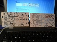
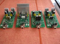
😱😱😱Continuing on the design, presented in Post #821, I have developed a diy-friendly layout of the "lite" version of Parallel amplifier (single output pair).
I can't test it myself - my lab is disassembled again - so, if somebody wants to try this cool creature - that would be great!
Nominal rails are +/-50V DC.
Cheers,
Valery
Valery,just a note.
I see this pcb ,i think that traces are thin and pads aren't ideal for hand drilling
Last edited:
I can't test it myself - my lab is disassembled again - so, if somebody wants to try this cool creature - that would be great!
Cheers,
Valery
Going some where good?
😱😱😱
Valery,just a note.
I see this pcb ,i think that traces are thin and pads aren't ideal for hand drilling
Ahha... it's a good one.
I will try to make them "fatter".
Going some where good?
Just leaving the place it occupied during the last few years - it will take some time to find the new place, likely closer to my home, and re-assemble everything

Hi Valery,
I will build it but I use iron transfer so I need your files mirrored from what you have posted. It would be nice if you could post one with see through showing the silk over the traces for easy troubleshooting.
And, Like thimios pointed out, maybe enlarge some of the pads a bit.
Thanks, Terry
I will build it but I use iron transfer so I need your files mirrored from what you have posted. It would be nice if you could post one with see through showing the silk over the traces for easy troubleshooting.
And, Like thimios pointed out, maybe enlarge some of the pads a bit.
Thanks, Terry
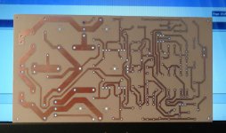
Parallel - updated bigger holes / fatter traces
Hi Terry,
Great! I hope, now it's easier to etch / drill.
I have printed the mirrored PDFs now.
Cheers,
Valery
Hi Valery,
I will build it but I use iron transfer so I need your files mirrored from what you have posted. It would be nice if you could post one with see through showing the silk over the traces for easy troubleshooting.
And, Like thimios pointed out, maybe enlarge some of the pads a bit.
Thanks, Terry
Hi Terry,
Great! I hope, now it's easier to etch / drill.
I have printed the mirrored PDFs now.
Cheers,
Valery
Attachments
-
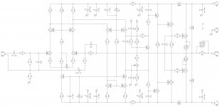 01-Parallel-LT-Sch 2.jpg282.4 KB · Views: 406
 -
z05-Parallel-LT-Bottom-mirrored.pdf40.3 KB · Views: 135
-
z04-Parallel-LT-Silk-mirrored.pdf69.1 KB · Views: 124
-
z03-Parallel-LT-Bottom 2.pdf40.3 KB · Views: 121
-
z02-Parallel-LT-Silk 2.pdf69.2 KB · Views: 152
-
z01-Parallel-LT-Sch 2.pdf47 KB · Views: 158
-
 04-Parallel-LT-Bottom-contrast.jpg610.6 KB · Views: 381
 -
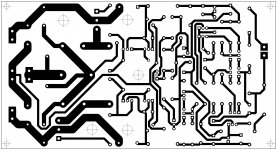 03-Parallel-LT-Bottom 2.jpg401.2 KB · Views: 366
 -
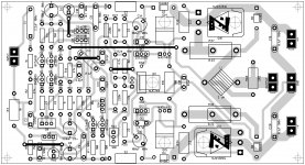
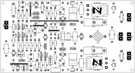 02-Parallel-LT-Silk 2.jpg534.9 KB · Views: 399
Yes... unbeatable 😎
I have already mentioned somewhere - in general, I think slower than Terry builds
I have already mentioned somewhere - in general, I think slower than Terry builds
A few traces close to the bias spreader are looking a little bit close to each other, but I believe it will be possible to separate them, right?
It really takes less than an hour. I had to wait for the wife to go to the store so I could steal her counter space. 😉
I have the holes drilled now. One nit pick if I may. If laying for etching it is nice to under-holes a little. It acts like a center punch and leaves more copper after drilling. I like to use a 6mm bit for the small resistors and caps. 8mm works fine too. I realize that you have to error to the larger size if they are through hole. I'm only speaking of etched single sided boards.
Blessings, Terry
Attachments

When I used to hand etch, I would make all hole sizes .025". This would leave a tiny center punch size hole in the copper for drilling. This worked especially well for larger ICs. Much more accurate drilling.
When I used to hand etch, I would make all hole sizes .025". This would leave a tiny center punch size hole in the copper for drilling. This worked especially well for larger ICs. Much more accurate drilling.
Right, I see. We need relatively big pads for better soldering and small holes for better drill centering.
Vertical CFA
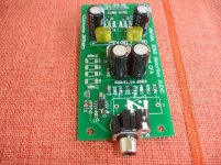
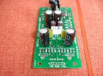
Great job!
Only the input caps are missing now, as far as I can see.
do you mean holes for the resistor leads?.............If laying for etching it is nice to under-holes a little. It acts like a center punch and leaves more copper after drilling. I like to use a 6mm bit for the small resistors and caps. 8mm works fine too. I realize that you have to error to the larger size if they are through hole. I'm only speaking of etched single sided boards.
Blessings, Terry
0.6mm or 0.8mm?
Great job!
Only the input caps are missing now, as far as I can see.
Thanks Valery,yes inp.caps are missing if you want MKP type.feedback resistors also missing(CFA amplifier) and some 100pf caps.I will built all with what i have and then i report what is missing.😉
- Home
- Amplifiers
- Solid State
- Revisiting some "old" ideas from 1970's - IPS, OPS