Member
Joined 2009
Paid Member
I got some diodes from a friend today do will see about powering up the soldering iron tonight. Last night I installed a noval socket in the experimental chasis too and looked at my tube stash to see what might be worth trying as a driver tube. I think it may be worth considering a voltage doubled supply for the driver tube when trying out a 12AX7 so that I have more headroom for a simple resistor anode load. I have some 6SN7's I can try, and a couple of other interesting choices.
Why not use a paralleled 12AX7, so that you have 2mA of plate current to sink into the load?
If you run the 2A3/6B4G/6AV5-triode low and hot (maybe V plate-cathode of about 250V, Ip of about 60mA or a little higher), the grid bias required should be about -45V. With a probable 50X gain achievable from the 12AX7 with diode bias or bypassed cathode resistor, you should be able to get that 2A3 to full power, just barely.
To get away from the need for a second higher voltage power supply, maybe you could put an active plate load on that 12AX7 (maybe an LND150?) which should allow you to get all the gain available despite the low B+ available.
Paralleled 12AX7 w/ active load --> 2A3 -or-
12AX7 w/ active load --> MOSFET source follower --> 2A3
Too complex?
The three stage 6SN7 --> 6SN7 --> 2A3 (or 300B) has been done to death.
Flesh And Blood The Reichert 300B Article By Herb Reichert

I heard that amp on a number of occasions, with a 300B. I remember it was pretty good, but a little 'dry' sounding. Maybe that would be nice using a paralleled pair of 2A3's instead of the 300B, after optimizing the driver a bit.
--
If you run the 2A3/6B4G/6AV5-triode low and hot (maybe V plate-cathode of about 250V, Ip of about 60mA or a little higher), the grid bias required should be about -45V. With a probable 50X gain achievable from the 12AX7 with diode bias or bypassed cathode resistor, you should be able to get that 2A3 to full power, just barely.
To get away from the need for a second higher voltage power supply, maybe you could put an active plate load on that 12AX7 (maybe an LND150?) which should allow you to get all the gain available despite the low B+ available.
Paralleled 12AX7 w/ active load --> 2A3 -or-
12AX7 w/ active load --> MOSFET source follower --> 2A3
Too complex?
The three stage 6SN7 --> 6SN7 --> 2A3 (or 300B) has been done to death.
Flesh And Blood The Reichert 300B Article By Herb Reichert
I heard that amp on a number of occasions, with a 300B. I remember it was pretty good, but a little 'dry' sounding. Maybe that would be nice using a paralleled pair of 2A3's instead of the 300B, after optimizing the driver a bit.
--
Member
Joined 2009
Paid Member
rongon, I've never heard the cascaded 6SN7 driver stage option but in principle I also would prefer a single driver stage. But this is Ron's project and he'd like to try it out to hear for himself - that's the DIY spirit !
I do like the idea of a Mosfet follower, more than parallel driver tubes. I don't have a suitable FET to hand so that would have to be ordered. Has anybody tried using an emitter follower, I have a stash of Bipolar transistors ?
I do like the idea of a Mosfet follower, more than parallel driver tubes. I don't have a suitable FET to hand so that would have to be ordered. Has anybody tried using an emitter follower, I have a stash of Bipolar transistors ?
Member
Joined 2009
Paid Member
So, I wired up the basic power supply. That's the 360Vrms secondary (180-0-180 at 250mA) from the Edcor power transformer feeding a bridge rectifier made up from discrete silicon diodes. The bridge is followed by a 1uF 500V russian PIO capacitor, then an Edcor 2H-300mA choke and then a 50uF 500V electrolytic. I used a 2k2 ceramic coated resistor as a dummy load which should give me a draw of around 150mA. Wires were twisted where they carried opposing currents to minimize current loops. The 6.3Vac heater secondary was left unused.
I measured 520V unloaded on the 2nd cap, around what I'd expect.
I measured 319V loaded on the 2nd cap, around what I expected from PSUD.
I measured 322V loaded, on the first cap corresponding to a 3V drop across the choke and consistent with a roughly 20 Ohm DCR.
I noticed that unloaded, the voltage went down pretty fast once power was removed, dropping about 100V in 30 seconds and then it seemed to decay more slowly. What's going on with that - a leaky cap ?
More worryingly, under load I was getting a fair bit of mechanical hum from the set-up. Enough that this is a show stopper for now. I can't spend long tracking it down, the load resistor gets very hot very fast so I'm going to have to make up a more thermally stable load in order to track down the hum. Unloaded there's a low level of hum. I don't like hum, if it's the power transformer then it's going to have to be replaced. I'll take another look at the set up tomorrow if I can.
Last edited:
Chokes ring and/or buzz if they get excited in a certain way.
I have a 7H 150mA (145 ohm DCR) choke I was trying to use with only about 20mA drawn through it. It buzzed like crazy, really easy to hear. So annoying. I gave up on it in that circuit, but later used it in a different circuit with 130mA going through it, and it works perfectly.
There's a discussion of this in Morgan Jones "Valve Amplifiers" but I can't find it atm.
--
I read through the thread. Those 2A3's and Sofia OPT's look nice.
If you decide to do a simple, three-stage design like all the various ones that use a 6SN7 and a 2A3, think about changing that 6SN7 to a 5687 (or its Russian near-equivalent, the $4 6N6P, or the JJ ECC99 tube is also very similar). You will need more current from your power transformer, but not much more.
What's so great about the 5687? Nothing other than that it has quite low plate resistance and fairly high transconductance, so it will drive the 2A3's grid very well, even possibly goosing a little into grid current before it gives up.
A 6SN7 triode's plate resistance (rp) is about 10k ohms.
A 5687, 6N6P, or ECC99 triode's rp is about 3k ohms.
The other advantage the 5687 has over the 6SN7 is that the 5687 can work reasonably well with a much lower B+ voltage than can a 6SN7. 6SN7 works best with B+ of 350V or higher, while you will probably only have 300V available.
Two stages of 5687, each with a stage gain of about 10X, will give you about 100X gain. That means you'll be able to drive that 2A3 to full power with only about 0.5V signal input. That's a nice spot.
With a 5687 and a 300V B+, a 10k plate resistor, and plate current of 15mA, the 5687 plate voltage (plate to cathode) will be about 150V and grid bias will be about 6V (cathode resistor = 390 ohms or so).
6N6P or ECC99 would use similar values, but have different pinout (wiring).
I think that would make a pretty goof-proof circuit that should work well. The 5687 is almost like a little power tube, which makes it a really strong driver tube.
--
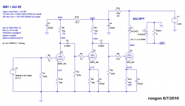
I whipped up a spice simulation of the circuit and it turned out really well. Or at least LTspice thinks it's good. Here's the circuit diagram (attached).
--
If you decide to do a simple, three-stage design like all the various ones that use a 6SN7 and a 2A3, think about changing that 6SN7 to a 5687 (or its Russian near-equivalent, the $4 6N6P, or the JJ ECC99 tube is also very similar). You will need more current from your power transformer, but not much more.
What's so great about the 5687? Nothing other than that it has quite low plate resistance and fairly high transconductance, so it will drive the 2A3's grid very well, even possibly goosing a little into grid current before it gives up.
A 6SN7 triode's plate resistance (rp) is about 10k ohms.
A 5687, 6N6P, or ECC99 triode's rp is about 3k ohms.
The other advantage the 5687 has over the 6SN7 is that the 5687 can work reasonably well with a much lower B+ voltage than can a 6SN7. 6SN7 works best with B+ of 350V or higher, while you will probably only have 300V available.
Two stages of 5687, each with a stage gain of about 10X, will give you about 100X gain. That means you'll be able to drive that 2A3 to full power with only about 0.5V signal input. That's a nice spot.
With a 5687 and a 300V B+, a 10k plate resistor, and plate current of 15mA, the 5687 plate voltage (plate to cathode) will be about 150V and grid bias will be about 6V (cathode resistor = 390 ohms or so).
6N6P or ECC99 would use similar values, but have different pinout (wiring).
I think that would make a pretty goof-proof circuit that should work well. The 5687 is almost like a little power tube, which makes it a really strong driver tube.
--
I whipped up a spice simulation of the circuit and it turned out really well. Or at least LTspice thinks it's good. Here's the circuit diagram (attached).
--
Attachments
And an update...
I threw a 6SN7 into the circuit, both with about 7.5mA plate current. First stage has a 22k plate load resistor, second stage a 15k plate load resistor. The low value on the second stage is because of the low B+. In order to get enough voltage swing out of the second stage, the value of plate resistor had to be kept lower than optimal so that there's enough plate to cathode voltage (and thus a 'tall' enough bias voltage).
The end result is that the 6SN7 works, and spice actually predicts slightly lower THD, but there's more 3HD than with the 5687 doing the driving.
So, as predicted, the 5687 does better in this particular instance because of its lower rp and higher transconductance, which allow it to work better with the low B+ voltage available.
--
Last edited:
Member
Joined 2009
Paid Member
Member
Joined 2009
Paid Member
^try dipping in polyurethane varnish several times....
Don't you need some kind of vacuum system for that to work or else all you do is coat the outside ?
You have a resonance formed by the 2H choke and the 50uF cap around the rectified conduction frequency. If it's the resonance causing the issue you need either bigger L or bigger C to drop the resonance down.
Another thing to note, using a CT secondary with a bridge rectifier that was intended for a full wave rectifier might be over stressing it given the same load conditions.
Another thing to note, using a CT secondary with a bridge rectifier that was intended for a full wave rectifier might be over stressing it given the same load conditions.
Member
Joined 2009
Paid Member
I did that calculation early on, 2H and 50uF has a corner frequency around 16Hz, not at the 60Hz/120Hz level ? Could I have something going on between the choke and the first cap - at 1uF ?
The power transformer is rated at 250mA at the HT secondary by Edcor. A pure choke input filter has unity power factor but I have a small first cap. However the resulting B+ is close to what a pure choke input would give - I was hoping this trafo is big enough ?
The power transformer is rated at 250mA at the HT secondary by Edcor. A pure choke input filter has unity power factor but I have a small first cap. However the resulting B+ is close to what a pure choke input would give - I was hoping this trafo is big enough ?
Last edited:
Hi Bigun, there is a resonance at 100Hz. 1/sqrt(L*C)
1 / sqrt( 2 * ( 50 * 10^-6 ) ) = 100
Which Edcor model do you have?
1 / sqrt( 2 * ( 50 * 10^-6 ) ) = 100
Which Edcor model do you have?
Hi, yes sorry.
15.9Hz, still slightly high.
With a bridge rectifier and a choke input filter you are getting what you should; .9 x 360 = 322v
Using the center tap and full wave rectifier you will be getting .7 x 360 = 252
I am guessing that since there is more voltage you can't use as much current on that secondary. i.e. Edcor is rating the secondary current of that transformer for a full wave rectifier?
Last edited:
Member
Joined 2009
Paid Member
I tried removing C1, tried doubling C2, no change in hum.
I disconnected the choke, the power transformer is silent with or without the load.
I believe the choke is choking 😀
I disconnected the choke, the power transformer is silent with or without the load.
I believe the choke is choking 😀
Don't you need some kind of vacuum system for that to work or else all you do is coat the outside ?
don't have a vacuum system yet my traffo builds are dead quiet...
you will be amazed at how how the varnish can get in between lams
where they are really needed...
Yeah, that's the thing about inductors and transformers -- resonances. Sometimes they can be really nasty. Like most 1:1 transformers will have an ultrasonic peak unless you put a damping resistor or zobel on the secondary. Some say they sound better without the damping, but I can't believe a +10dB peak at 30kHz can be good for your tweeters.
Anyway, yes, I can see how a 15.9Hz resonance could cause a choke to vibrate loudly. Why not use bigger value capacitors? With only 2H I'd intuitively choose 100uF at least.
This Nichicon 220uF 400V cap has a 1.2A ripple current rating and +105C temp rating. Something like that?
This Nichicon 330uF 400V cap looks like a beast. 1.4A ripple current rating.
What kind of choke is it? What's the DCR?
--
I think it's probably a good idea for the corner frequency to be 10X lower than the frequency of interest. So if you're filtering out 120Hz, I think you want the corner frequency to be 12Hz, or preferably lower. In the texts I've read, the goal is usually to get the corner freq down to 1.5Hz or thereabouts.
Using this online tool --
(Sample)RLC Low-pass Filter Design Tool - Result -
-- it looks like for a choke with L = 2H and DCR = 60R, you'll need C to be a whopping 470uF to get to a corner freq of 5Hz.
So yeah, it looks like even 100uF is not nearly enough. I think...
--
If you put into that calculator R = 65, L = 2H, and C = 50uF, and check the Impulse Response option, you'll see the resonance at 15.9Hz and the ringing of the filter in the impulse graph. Interesting.
--
Last edited:
Member
Joined 2009
Paid Member
Why not use bigger value capacitors? With only 2H I'd intuitively choose 100uF at least.
When I wrote that I doubled C2 it means I increased from 50uF to 100uF yet there was no change to the hum.
- Status
- Not open for further replies.
- Home
- Amplifiers
- Tubes / Valves
- 2A3 driver