Thats good news!
Ok i got Some findings!
The paper i bought Looks like carton, it feels thicker then the previous used 120 grams. While this is 130 grams. A thing of interest , is the fact it bends more easy in one direction. When looking closely you can see it has a pattern on it which makes it easy to bend in one direction. I used the hot iron method to bond but this time it failed the heated part will bend 🙁 so it won't pass the gap without touching the metal. **** !!!! But I did measure it even with this unbearable distortion I could still see if this more heavy material will cut off the highs. And behold it did not, It extends as far as the far less stable paper. Making the cylinder more butterfly shape smoothed the peak at the end. and now it almost looks the same as the more crappy paper. Tonight if I got time I will make a new one but using superglue for the bonding, I bought some pe masking tape that should not stick to the super glue so I can make a straight glue joint without the glue running everywhere. So more to follow on this paper ! By the way I used a single coil, the high end looked better on a sandwich single coil design.
Last edited:
One more thing your latest measurement could be almost correct. But there is something weird you drop almost 20 dB before rising 20 above the overal level , That's a swing of 40, I really hope this is the technical fault🙂
Hope you get you preamp soon 🙂
I bought mbox2 pre amp they are cheap 35 should get you one . It's a sub soundcard wirh 2 preamps with phantom
Hope you get you preamp soon 🙂
I bought mbox2 pre amp they are cheap 35 should get you one . It's a sub soundcard wirh 2 preamps with phantom
Thats good news!
Ok i got Some findings!
The paper i bought Looks like carton, it feels thicker then the previous used 120 grams. While this is 130 grams. A thing of interest , is the fact it bends more easy in one direction. When looking closely you can see it has a pattern on it which makes it easy to bend in one direction. I used the hot iron method to bond but this time it failed the heated part will bend 🙁 so it won't pass the gap without touching the metal. **** !!!! But I did measure it even with this unbearable distortion I could still see if this more heavy material will cut off the highs. And behold it did not, It extends as far as the far less stable paper. Making the cylinder more butterfly shape smoothed the peak at the end. and now it almost looks the same as the more crappy paper. Tonight if I got time I will make a new one but using superglue for the bonding, I bought some pe masking tape that should not stick to the super glue so I can make a straight glue joint without the glue running everywhere. So more to follow on this paper ! By the way I used a single coil, the high end looked better on a sandwich single coil design.
Hi Wrine,
Interesting things you have found, but with NO pics... 🙁
I thought that double coils should add some more dB; strange thing.
Cheers
Sergiu
One more thing your latest measurement could be almost correct. But there is something weird you drop almost 20 dB before rising 20 above the overal level , That's a swing of 40, I really hope this is the technical fault🙂
Hope you get you preamp soon 🙂
I bought mbox2 pre amp they are cheap 35 should get you one . It's a sub soundcard wirh 2 preamps with phantom
Well my friend you are right, maybe it is a technicall prob. Today i received my borrowed preamp and will measure soon (after i solder conectors to the wires).
In the meanwihile i dont want to buy another psu and other stuff because let me tell what i did: Phantom psu with regulated capacitance multiplier
(48V@1a) from JLH amplifier site (way better than cheap phantome ones) and low esr nichicon caps all the way; all the things are matched here (including caps) all of this for only aprox 19 bucs 😀.
Today i found a discrete mic preamp schm specially designed for electret mic (from my books) with very low noise and linearity; this morning i got to the shop and buyed all of the components, painfully matched (luckily that i worked there in the past and the seller let me match all the components) all of them for only 10 bucs. I buyed a small trafo and want to go on "the valve passive filtering way" (CLCLCRC) wich i also measured very good in the past...
So this will be the way for me. 😀
Till the owner of the borrowed preamp will come, i will slowly making this diy preamp.
I want to thank you very much for showing me that diy way is the best way. 😉
Cheers
Sergiu
Well i am Not sure iTS the best way it is the fun way 🙂
About the mbox iTS a USB device No other stuff Needed only USB cable an the mbox, I did Not loopbacked it , since i Dont even use the preamp since i got an umik 🙂
I Will try to make a video Or pics when i make a new one. Having 1 coil Or 2 did Not do major things in spl as i remember , but noticable is the drop in high freq.
I should make a direct comparison. I also ordered verry Cheap 1 mm thick magnets. 40x20x1 almost 4 times as weak compared to my 5 mm Magnets . But i should be able to make a big one that reaches lower without running in insane costs. Efficiency wont be that high. One pro in using thin Magnets is that the coil in the midlle Will be lighter! If you use 10 mm thick Magnets you have 10 mm of paper holding the coil that wont be of any use.
Aah Well that my theorie 🙂
Last edited:
hmm i made a new one with the regular super glue to bond the 2 halves, i used this new paper again and 1 alu coil. nice steady without the buzzing and crap. i plays rather nice but there are a few insane distortion peaks like nodes seen in DML's, for instance the biggest peaks was at 160 hz next one at 320, when i generate a tone at 160 my analyzer thinks it is 320 🙂 haha. its emitted mostly from the edges of te paper. so a way to terminate the resonances is a must. just like in most DML speakers with exciters the edge can make weird sounds. a way of termination should be found, the weight of the PVC foam tape helps, a bit it lowers these distortion peaks in frequency as well as the strength. well loads of room to play with this design again 🙂 tackled high end extension and most of there huge peaks normally seen in rubanoide measurements (up high). now gone aim at the distortion from MODES. going bigger might shift them drastically downwards.
its by no means perfect, but making slow progress so far
i will post measurements and other media when i got some more time.
its by no means perfect, but making slow progress so far
i will post measurements and other media when i got some more time.
Last edited:
Well i am Not sure iTS the best way it is the fun way 🙂
About the mbox iTS a USB device No other stuff Needed only USB cable an the mbox, I did Not loopbacked it , since i Dont even use the preamp since i got an umik 🙂
I Will try to make a video Or pics when i make a new one. Having 1 coil Or 2 did Not do major things in spl as i remember , but noticable is the drop in high freq.
I should make a direct comparison. I also ordered verry Cheap 1 mm thick magnets. 40x20x1 almost 4 times as weak compared to my 5 mm Magnets . But i should be able to make a big one that reaches lower without running in insane costs. Efficiency wont be that high. One pro in using thin Magnets is that the coil in the midlle Will be lighter! If you use 10 mm thick Magnets you have 10 mm of paper holding the coil that wont be of any use.
Aah Well that my theorie 🙂
Hi Wrine,
Your right. I like the fun way more. Yesterday i found out that the borrowed preamp wasnt good so i had to build my preamp from scratch. I have to make a psu and some tests and maybe tomorrow will be back on track...
Your right about the coil:10 mm could bend really easy and could be a mess if humidity is involved but i did measure some sounds that could linearise the frecv resp, coming from there. Did you measure the interior sounds of the cilinders coming from there?
Cheers
Sergiu
hmm i made a new one with the regular super glue to bond the 2 halves, i used this new paper again and 1 alu coil. nice steady without the buzzing and crap. i plays rather nice but there are a few insane distortion peaks like nodes seen in DML's, for instance the biggest peaks was at 160 hz next one at 320, when i generate a tone at 160 my analyzer thinks it is 320 🙂 haha. its emitted mostly from the edges of te paper. so a way to terminate the resonances is a must. just like in most DML speakers with exciters the edge can make weird sounds. a way of termination should be found, the weight of the PVC foam tape helps, a bit it lowers these distortion peaks in frequency as well as the strength. well loads of room to play with this design again 🙂 tackled high end extension and most of there huge peaks normally seen in rubanoide measurements (up high). now gone aim at the distortion from MODES. going bigger might shift them drastically downwards.
its by no means perfect, but making slow progress so far
i will post measurements and other media when i got some more time.
I also found that using more super glue resolves the buzzing probs.. in my first listening trials i also found some strange sounds coming from the ends of the cilinders (lateralls) when deflected with a roll of paper. This means that the peaks and resonances generated from the active portion travels trough the membrane straight to the edges where is fastened.. The results could be a tamed elegant sound reflected like an incredible surround to the public or like a huge pile of crap when the volume is up. At lower levels everithing its ok at my bigger version but at high volume i need some damping too somewhere in the medium frecv.
I still have to see wich version extends the hights higher but at this moment i'm stuck with the mic problem.
I hope that i will resolve my issue soon.
Cheers
Sergiu
I hope so to serg! I might need to look at Some dmldesign to see if they found a solution to the distorrtion found in panels with exciters.
I as Well need to rebuild my 30 cm ruba to see if going from 20 to 30 cm lowers the distortion in the freq domain, and to See if it extends the low end , and by what margin. So i got an idea on how big a ruba needs to be to extend to 100 Or so. 🙂 would be awesome. But first small steps.
I as Well need to rebuild my 30 cm ruba to see if going from 20 to 30 cm lowers the distortion in the freq domain, and to See if it extends the low end , and by what margin. So i got an idea on how big a ruba needs to be to extend to 100 Or so. 🙂 would be awesome. But first small steps.
Last edited:
I hope so to serg! I might need to look at Some dmldesign to see if they found a solution to the distorrtion found in panels with exciters.
I as Well need to rebuild my 30 cm ruba to see if going from 20 to 30 cm lowers the distortion in the freq domain, and to See if it extends the low end , and by what margin. So i got an idea on how big a ruba needs to be to extend to 100 Or so. 🙂 would be awesome. But first small steps.
Hello my friend,
I have a proposal to make: to be more efficient, lets make a list with all of the aspects achieved and to achieve. Lets make a structurated list so that we dont do the same things both. What do you say?
Hello my friend,
I have a proposal to make: to be more efficient, lets make a list with all of the aspects achieved and to achieve. Lets make a structurated list so that we dont do the same things both. What do you say?
After rereading some of the posts in this thread i made my mind. There is too much too write down. I think i will print all the thread and thats it. There's no time for tables.. 😀
Ok if i would make a list this would be it (i might forget some)
tests
- Overhung/underhung coil
- Smaller magnets , and go larger vertical for 2 reasons.
1 #
50 cm ruba will bundle high frequency insanely so you would have to sit in front of them, making them larger in a baffle or a stand that will give it a slight angle upwards. will give good high frequency's when sitting standing or sitting on a diner chair etc.
2#
When go large you dont need 300 pounds of force , that much eficiency is not usefull. first the limit of how loud it can play sis either the low frequency's or your ears at the higher frequency's. if you would make one that only plays from 300hz with a steep filter (24dB) then having high high high efficiency is good and makes it be able to scale down in the horizontal pane, and make the power handling lower and thus weight of coil and the need for stiffer material.
- making the circles wider? or smaller ?
what happens? does it lower the freq it can produce ? i tried it several times with not sturdy enough paper i think and nothing much happened. but i still wonder what will happen. since why are the circles as wide as they are? why not smaller ? what will happen ? My thought is. making it smaller might hurt low end a little. but high freq will benefit, since the void in between the circles that produces the highs will be less deep.... so less out of phase material at high freq. also it would be able to dismiss the butterfly config creating a hinge. by making the circle smaller you will decrease void gap so there is no need for the butterfly, and this will result in slightly better controll of the paper in the lower end.
- what is the benefit of using back and front circles ? if any ?
I know symmetry, but does it translate into something in the measurements ?
i did many measurements with front and back, then cut of the back. but i must say i am pretty terrible in keeping measurements organized or keeping them at al! what remains in my mind that diferences where not there, except for losing the weird out of phase peaks and dips in the version without back circles.
- How to damp the Modes ?? especially the edges on top of the circles? and near where the paper meets the construction. what will different heavy material or rubbers do in these places >?
- using a smaller coil then the circles are in height?
so using a 20 cm coil on a 30 cm ruba ? what will happen does the extra length still add to the low end ? or lower the MODES ?? i think they will lower the modes and thus a cheap way to get them down out of the usable area. BUT what will it do to the high end since the construction is more heavy but not driven over the entire area ?
- Using higher impedance coils.
what happens to eficiency from 1 coil to a 2 coil in series >?
My thoughts, using one coil with smaller traces wil save weight in acrylic adhesive from the tape, and super glue for attaching them. also 1 coil can sit in between papers to have the best possible contact with the papers.
Coating this new paper with something like super glue?
what will happen using coating or not>? does it still do anything to high end ? does it cripple the low end?
well thats it for now, i am sure i come up with another 100000 things but this is it for now.
one last thing i ordered this weekend magnets from the site i gave you, and received them today..... thats very fast.
Last edited:
Hello again my friend. Thanks for the list. I apreciate it.
I also have a bunch of questions to add too. Tomorrow morning i will put down my thoughts too. I hope that we can make a list from our questions with what to do, and not to, what has been tested and what not. I think that this way we can know in what direction to go and what to search for. What do you say?
I think that we are doing allot of things (tests) at the same time without having a precise direction, like some chapters to solve or to be solved. You can modify it as you wish and add what you found. Also add questions too.
Lets begin:
1. The magnets:
*Should they be bigger or smaller in lenght?
Smaller could be costly to acieve the same strenght, but longer could be cheaper if they achieve the same force togheter.
*should they be taller or thinner?
NA (i dont have funds for buying magnets again)
*should they be weaker or stronger?
Stronger it will ad some dB but if the cilinders are not proprely damped and designed those dB's could drive you insane because of the nasty resonances amplified. Also stronger magnets will add dollars in plus to the metal plates (more thicker,or other steel ads more money to the count).
2. Metal plates:
*A very important thing that nobody answered yet: should the plates be 2cm+1cm width so that the flux would be more concentrated or other dimensions like 2+2cm would
be also good?
I use the second solution with 2+2cm width because i seen that Wrine's 3cm version bended at 3mm gap. Normally the gap is 4mm, but because i used bigger plates i got 3mm gap without bending.
*what material to use for the plates?
A37 french steel was used in the original design.
AISI 1018 was also used with succes.
Romanian equivallent is OLC15X.
We use colld rolled steel now with succes and i think that with weakened magnets like n42,n38 standard AISI1017 steel can be used also.
It seems that a larger quantity of carbon diminishez the force and lesser carbon improves force further but saturates more easier. So it must be just as its needed, not too much nore too little quantity of carbon.
3. The gap:
*2,3 or 4mm?
4mm for n48 magnets its perfect, smaller gap could bend the steel..
3mm ads some dB and its the limit of suportability because you can barely keep the coil centered, and as it is the coil could bend from humidity and rub on the plates causing distorsions easily and eventually take the output trannies to their graves as they did to mine 😀 .
2mm doesnt add to much stuff, its very hard to center and keep centered the coil. Also if the coil bends only a little bit disaster will strike.
4. The coil:
*single sided or double sided? SERIES OR PARALEL? PARALELLED PHASED, OR ANTI PHASED?
NA
*Copper or Al?
I found that wirewound copper its very painfull and exhausting and found allot of problems to bonding and keeping it flat..
Flexible copper pcb is a good and very fast sollution, but still too heavy. If it were for me i woul search for a coil made from flexible band that was used in the old walkmans (for the screens and push comands).
For the moment diy hand made Al coils are the winners. They are light, flat, easy to bond and have good contact with the cilinders and now we have flux to solder Al (thanks Wrine).
*overhung or underhung?
NA
5. The paper (what kind was tested? impregnated?speacial treated)
Will add info tomorrow.
6. The cilinders (dims, diams, shapes)
Tomorrow
7. The cuts
8. Suspensions
9. Glue used
10. Dampening
There are allot of things to add as you see but we can do it. This way we can see clearly what to do.
What do you say Wrine?
Cheers
Sergiu
oh one thing i used 20 mm x8mm cold rolled steel that bended with a 3 mm gap. and for the coils i used the same method for the alu as i used for the copper PCB so its a propper coil just like the walkman but in aluminium, without the heavy epoxy board 🙂 i never made a picture of it i think? ill try to make some pictures this weekend. i might try to get hold of some thinner metal like 20x 6 mm for the thinner magnets of 40x20x1mm they are not strong at all 🙁 they should be 3 weaker as my 5mm ones but it feels even less 🙁 tobad another 66 euro down the drain. but still i will make a rubanoide with them just to see how much worse they perform , since i bought 84 of them to be used in 2 ruba's of 80cm. (if my paper is even that size ) to see if i can cut costs get lower and still get enough SPL to mate to a woofer.
by the way, i could make you an a4 paper with printed alu coils on it, then etch it and send them to you for some tests if you want. maximum height is 29 cm. but i could fit 5 or 6 on one sheet. so you got 6 coils to experiment with without the pain stacking work of cutting them by hand? just send me a drawing (BMP) i use sprint layout for that , nice program where you can make square coils and hten just extend them to the size you want.
i think we should concentrate on the most important steps first
costs,getting lower,get rid of the modes(damping). since our previous problem was getting high enough kind of is solved... and i would like to drop efficiency to since it will always be used with some sort of woofer and most woofers unless PA are not that high in efficiency. so a region of 87 to 92 would be great i believe
Going large will solve 2 problems, costs of magnets i believe and getting lower.
one last note
PARALELLED PHASED, OR ANTI PHASED? anti phased would result ,in a perfect world into .... no sound. so anti phased will never work.
Last edited:
I am really sorry to hear that my friend. Magnets are costly indeed. 🙁
Yes i didnt knew you had that kind of coils. You sayd nothing about them. 😀
Of course i want some coils. I will try to make them tomorrow and send them to you.
"costs,getting lower,get rid of the modes(damping). since our previous problem was getting high enough kind of is solved... and i would like to drop efficiency to since it will always be used with some sort of woofer and most woofers unless PA are not that high in efficiency. so a region of 87 to 92 would be great i believe"
That's the direction we need. We needed a plan.
And yes i agree with you we can drop the dB. Now i have two 15" woofers refurbished from PA, but others dont have such things. I cannot go lower with these magnets because my magnets are assembled but i can try smaller coil with bigger membrane.
"Going large will solve 2 problems, costs of magnets i believe and getting lower.
PARALELLED PHASED, OR ANTI PHASED? anti phased would result ,in a perfect world into .... no sound. so anti phased will never work."
Maybe youre right but maibe we should test this also. Who knows..
Going bigger might dampen some peaks and hight frecv, but we can increase them with cuts so no prob here.
Today i just finished the mic preamp, all assembled in a small opened and shielded case. Tomorrow will test and hope to finish this preamp issue once and for all.
Cheers
Sergiu
I hope it works !!! Looking forward to the measurements . About the spl you hot Sting Magnets so thats great, no need to go weaker 🙂 if you got them already hehe
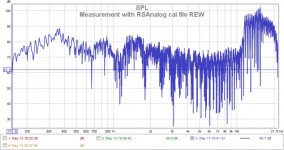
These are the measurements. It is a really strange thing. With a different cal file and a preamp i get similar measurements. The strangest things of all is WHY these two programs measure different?????!!!
😡😡😡😡😡
Can you see any problem here Wrine?
Do you have any video tutorial of how to measure with HOLM please?
Thanks in advance.
Sergiu
😡😡😡😡😡
Can you see any problem here Wrine?
Do you have any video tutorial of how to measure with HOLM please?
Thanks in advance.
Sergiu
Attachments

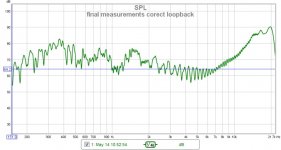
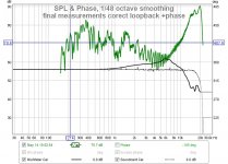
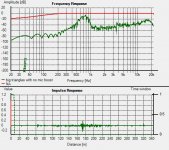
Here we are Wrine,
After almost a whole night loosen, and after reanalising the whole thing and graphs over and over again i have learnd some things and foun out the problem. There where three big problems in REW:
1. the loopback cable was way too long and had some leaky joints (now i use a short one without joints)
2.REw its pretty strange, BUT FIRST you have to measure the soundcard (hit calibrate);
3. Then hit MAKE CAL, AFTER measuring the souncard and your good to go.
I did all these steps incorectly because this is my first contact with this stuff and didnt know how to do it...
Now what i really believe, is that HOLM is doing a souncard cal and loopback, and dac cal at the same time. When i changed the loopback wire everything was very good and back to normal here.
If you look at the graphs bellow you will see what i meant when i said that REW is strange. There must be some settings there that i still dont know how to use and they are ruinig abit the measurement because i dont perceive, subjectively, a huge amount of hights.
I think that holm is very accurate here and its the program to use.
Look bellow and please tell if i'm wrong Wrine.
These measurements are from THE CLASSIC RUBAN with reactangular cuts in the active portion and round cuts in the middle of the coil.
Cheers
Sergiu
Attachments
- Home
- Loudspeakers
- Planars & Exotics
- A DIY Ribbon Speaker of a different Kind