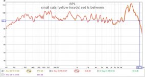
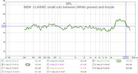
Here is the classic small cuts, double coats of laq.
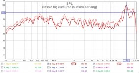
THe smooth results from earlyer wHWERE FALSE results because the LAQUEUR didnt hardened well. These are the correct plots inside a traingle and between two of them.
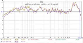
As you can see Wrine, both regions are working and correcting each other, and it is also visible at the classic small cuts. So in conclusion that the gap from 8khz its not problem at all. The biggest problem is the 11khz to 20khz... 🙁
THe smooth results from earlyer wHWERE FALSE results because the LAQUEUR didnt hardened well. These are the correct plots inside a traingle and between two of them.
As you can see Wrine, both regions are working and correcting each other, and it is also visible at the classic small cuts. So in conclusion that the gap from 8khz its not problem at all. The biggest problem is the 11khz to 20khz... 🙁
Attachments

Last edited:
Nice , what i think you should try is eliminate on side of pruducing highs, for instantie use cuts on only one Side , since the dip is phase related . Either by the use of two cylinders or the fact it transmit highs over a longer distance then 3,4 cm half a wave length of 10 kHz witch will then be out of phase. Just a theory.
I want to try the same but to give one side of the coil just enough damping to eliminate one of the cylinders to transmit high freq. so phasing won't concur, might lose some of the spl at 4khz-10 not sure yet
One last thing we should do is measure polar responses since it matters if you are on axis or a few degrees of the whole plot and curve wil change ( something I don't want ) for now best freq response without dip is slightly of axis either left or right , try it you will see
This is because of phase issues and I don't want my head in a veice, or I would make a big unsegmented esl since there distortion is lower 🙂
Last edited:
Btw what was the paper you used , I forgot the name and I will visit an arts store soon do I can take some with me to test 🙂
Btw what was the paper you used , I forgot the name and I will visit an arts store soon do I can take some with me to test 🙂
Thank you my friend. The paper is Canson "C"A Grain Paper 120gr/sqm.
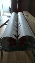
To tell you the truth, I wanted to keep a secret surprise but i cant keep it. 🙂 Here is my secret card (surprise ruban) that i want to test to see if it dampens the hights without eliminating any cilinder. Look in the pic bellow and you will see what i mean.
It is a double sided underhung coil in series with all the flavors included: cuts of course (round inside the coil and outside BIG cuts as in the classic vers combined with 50% laq because this was the best in my measurements). Just putting the coils in series makes a half cilinder lower in dB and this way dampens and lowers the reflections from it AND if you look carefully at that base former in the middle of the coil you will see that ( i have allready the dims in my head) the perpendicullar reflections comming from each cil and creates phasing will not produce this effect anymore instead they will bounce onto this formers surface and disperse into the room. Its purposelly thinked with smaller width because the sound comming from the rest of the cils (to the outside) will allready disperse away without creating this phase.
Making the coil underhung will compensate the addenum of the former and the series coils with an increase in dB. Another aspect that can compensate the "series coils aspect" (one coil will be louder than the other) so that we could barelly hear it is to put the + from the signall thats comming onto the + of the coil from the right cilinder from the right channel and the signall + on the left cilinder from the left channel.
The quantity of laq added to the former or not, or the cuts that should be done here remains sujcect to tests...
This is my theory and i want to test it. What do you say Wrine, should we give it a try?
Cheers
Sergiu
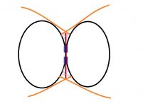
PS: orage and pink collors represents the sound waves.. 🙂
Attachments

oh i dont understand to be honest 🙁, if i lok at the picture i see 2 coils. and the rest looks like a normal ruban. how does it limit the High freq to on cylinder? one way would be filtering butn i dont seen that in the explenation. (using a coil) using just 2 coils in series will net spl in 2. i mean both coils see the same current. so either you have one coil with less turns and low impedance and one with high turns and high impedance. then still this would only work if i understand correct if you would use them paralel.
If you see current as a a water sewage system or pipes or whatever, the smallest pipe dictates what the maximum flow will be so in this case the smallest coil. so in the end they both have the same current going. and there wont be much difference.
if you would like to use 2 coils to split witch cylinder gets high frq you would need to use a low pass coil, so one only emits lows and the other does it fullrange..
To me the trick would be without any filtering. but hell if a small coil would fix the problem (since it is in the 10Khz region a very very small coil is needed) i would at least try it and maybe even fix it for only 1 euro 🙂, it does mean we need to voice coils. to seperate high from low, and there still would be a problem of the fullrange coil driving the low frequency cylinder.
Serg do you have skype ? i just now though about why we never ever just called each other and talks things trough , would be much faster 🙂 haha, ill send you a pm
BTW the orange soundwaves is exactly what i found out as well, this is how the high frequency's are emited. one these axis you get the best response in the high end!!!
Last edited:
Hello my friend ,
I aded you on skype. Will enter monday to talk. Send me a msg with the hour when your online.
Cheers
Sergiu
I aded you on skype. Will enter monday to talk. Send me a msg with the hour when your online.
Cheers
Sergiu
Hello again,
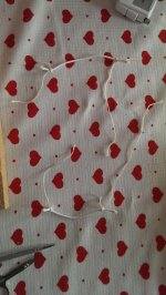
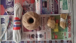
I'm back in bussiness. Just tested some new stuff today: elastics and ropes and internall dampening.
Conclusion: the softer the elastic is, the higher you go with the peaks and even higher with distorsion. The more tensionned you add to it, the dist goes down to almost half..
Another important aspect is that when tensionning the elastics more, the sounds comming from insyde the cuts vs between the cuts are almost the same (in a good way), except at the hights where each "covers" the other abit (the sounds from insyde and between the cuts).
Another aspect is that the ropes are a NO GO because they dont keep the coil in place at high peaks and large movements.
Thinner elastics vs thicker ones: the thinner the elastic the weaker the strenght, the higher the distortions. I use now a big elastic composed from 8 small elastics wich was the best for me..
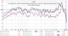
The cottone dampening from insyde must be insyde because the peaks that you see from my measurements (except those from 11khz to18 khz) are even higher and larger with no dampening. So the adennum of the cottone dampening insyde is very good. Here are some pics with high tensioned elastic and internall dampening and big cuts vs small cuts ON THE CLASSIC VERSION
.
I'm back in bussiness. Just tested some new stuff today: elastics and ropes and internall dampening.
Conclusion: the softer the elastic is, the higher you go with the peaks and even higher with distorsion. The more tensionned you add to it, the dist goes down to almost half..
Another important aspect is that when tensionning the elastics more, the sounds comming from insyde the cuts vs between the cuts are almost the same (in a good way), except at the hights where each "covers" the other abit (the sounds from insyde and between the cuts).
Another aspect is that the ropes are a NO GO because they dont keep the coil in place at high peaks and large movements.
Thinner elastics vs thicker ones: the thinner the elastic the weaker the strenght, the higher the distortions. I use now a big elastic composed from 8 small elastics wich was the best for me..
The cottone dampening from insyde must be insyde because the peaks that you see from my measurements (except those from 11khz to18 khz) are even higher and larger with no dampening. So the adennum of the cottone dampening insyde is very good. Here are some pics with high tensioned elastic and internall dampening and big cuts vs small cuts ON THE CLASSIC VERSION
.
Attachments

nice!!, so the cuts dont do all that much. since they are almost the same. funny the elastic thing i encounterd yesterday as wel. i had my elastics all up to the point they dont have any elasticity and it worked best. one other thing where is this measured on axis ? since i still see a dip in my measurements when you measure straight on axis the dip before the peak you know. of axis it smooths but thats not the goal 🙂 i eliminated one cylinder from producing highs but as we already suspected it is more the the fact highs are emitted from where the cylinders meet up to where the cylinder bows back to the structure. and especially the first 1-1.5 cm is creating the shark teeth. when i damp the cylinder after lets say 1 cm with from where the cylinders meet with something heavy the top end smooth out. but then again lose some sensitivity overal. and maybe the extend of how high it reaches.
so looks again like no free lunch. i though as well about making the cylinders smaller would als make the void between the cylinders less deep. so the peak and null should shift up. problem is if i want it out of the audio bandwith the void should not be deeper then 9-10 mm. that would be a verry small cylinder 😉
so looks again like no free lunch. i though as well about making the cylinders smaller would als make the void between the cylinders less deep. so the peak and null should shift up. problem is if i want it out of the audio bandwith the void should not be deeper then 9-10 mm. that would be a verry small cylinder 😉
Well the cuts did something but only till the point where the elastics are not tight or if hinges are used.. They did smoothen the frecv response good.. I think the cuts have effect when the active portion its abit loosen. As a matter of fact i sincerely do think that, subjectivelly speaking, these speakers sounds better when the elastics are loosen (or not so tight). I liked them more with the elastics loosen. Did you feel the same?
When the elastics are weakened they sound fuller, richer and have abit more dinamics. Could this be because, maybe, i say maybe, because of the phasing phenomena caused in the face of the active portion?
My measurements are allways on axys. That peak from 11 to 18khz drives me creazy.
Will have to test something tomorow: how much cuts do i need at maximum, and how they affect the overall frecv responce and sound + one cilinder smaller than the other.
And after all these infos are veryfyied and tested i will try the variant that i proposed earlyer and you sayed that you dont understand the painting . 🙂
Now let me say what i wanted to paint there: the blue lines are the coil underhung (half on each syde of the former), the red line is the former for the coil (its NOT the coil) and its purposelly bigger, and i measured exactly as you sayed and it seems that we dont need it to extend outsyde from the glued cilinders zone more than 2 cm. This way i think will deflect outsyde the hights from both cilinders and smoothens the 11-18khz peak. The pink dots represents the sound wich i think it will be like compressed in that small space and deflected outsyde of the active area in the directions pointed (showed) by the orange lines.
Its good to know that you chopped one cilinder off and now we know whats the result.
Cheers
Sergiu
Attachments

HEllo Wrine my friend,
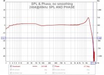
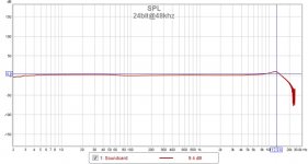
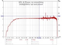
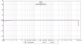
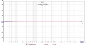
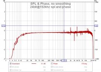
I seems likei did not taked into accountthe soundcard dist, spl, and phase... Please have a look at the cal files from bellow. As you can see at the spl and phase. Our problem might have been a soundcard problem from the start..
I upsampled my soundcard from 16bit@44100 up to 24bit@192000. I posted only the 24 bit samples because i had that dip on each 16bit setting, but from 24bit@96khz and up things smoothens. So this may have been a hardware thing from the start.. 🙁🙁😡😡😡😡 Will measure all the things again and repost.😡😡😡
Here are the cal files in jpeg (its easyer to see this way).
To be honest i have choosen for now the 24bit@96khz.😉
Cheers
Sergiu
I seems likei did not taked into accountthe soundcard dist, spl, and phase... Please have a look at the cal files from bellow. As you can see at the spl and phase. Our problem might have been a soundcard problem from the start..
I upsampled my soundcard from 16bit@44100 up to 24bit@192000. I posted only the 24 bit samples because i had that dip on each 16bit setting, but from 24bit@96khz and up things smoothens. So this may have been a hardware thing from the start..
🙁🙁😡😡😡😡 Will measure all the things again and repost.😡😡😡Here are the cal files in jpeg (its easyer to see this way).
To be honest i have choosen for now the 24bit@96khz.😉
Cheers
Sergiu
Attachments
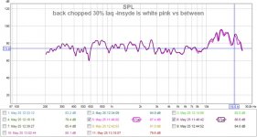
Here are the new measurements @24bit@96khz.
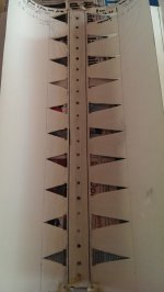
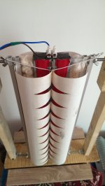
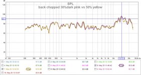
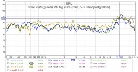
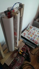
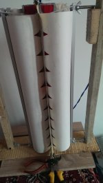
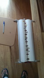
I have added some pics with classic small cuts, big cuts (its on the same speaker) and chopped back (you can see from the pics that the back has allot of cuts).
As you can see, now, with this new cal that 10 to 20khz isnt that high, and this should be because you didnt perceived (subjectivellly) the pesky hight peaks..
THESE ARE THE CORRECT MEASUREMENTS. I'm sorry for missleading you all.
The best from all of them is the CLASSIC variant with small cuts, and you cand see in the "VS" graphs why (there you will find the best measures from each).
Conclusion: the cuts have to be not higher than the 30% wich means 5.5cm hight in the active area, and no more or less than 2.2cm base lenght (when they are cutted they remain like a equilaterall triangles like in the pic with the membrane bellow) and NO MORE THAN 10 PCS. The base of the triangles has to be equal with the space between the cuts . If you do them higher then the coil tends to bend, if you make them with the base bigger (more than 2.2cm) or make more cuts than 10 not only that will make the coil bend but this will favoryse the peaks, dips and distorsions, and i think this is definetly has to do to the fact that you make the space between the cuts smaller, and this space linearise the frecv resp and dampens the peaks.
Also, two layers of laqueur smothens the overall frecv response and enlarges the sweets spot.
This is what i found today. If i think more deeper now i dont want to try to measure the ruban with a cilinder bigger and the other smaller because the smaller one will not emit hights anymore wich is a consequence for making it too rigid..... So i dont want to try it, instead i will show an surprise config in my next post Wrine wich i think will blow you away (literally!) because it smothes the 10 to20khz peak.
Please be with me.
Cheers
Sergiu
Attachments
-
 back chopped 30% laq -insyde is white pink vs between.jpg73.4 KB · Views: 139
 -
 IMAG0129.jpg850.5 KB · Views: 166
 -
 IMAG0143.jpg896.5 KB · Views: 138
 -
 IMAG0144.jpg960.6 KB · Views: 120
 -
 IMAG0145.jpg323.8 KB · Views: 125
 -
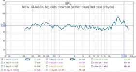 NEW CLASSIC big cuts between (wither blue) and blue (insyde).jpg72.2 KB · Views: 141
 -
 NEW CLASSIC small cuts between (White greeen) and insyde.jpg71.4 KB · Views: 121
 -
 NEW chopped 30% vs 50% (yellow) laq.jpg72.2 KB · Views: 115
 -
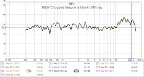 NEW Chopped (insyde is black) 50% laq.jpg69.5 KB · Views: 121
 -
 small cuts(green) VS big cuts (blue) VS Chopped(yellow).jpg143 KB · Views: 121
Now my surprise:
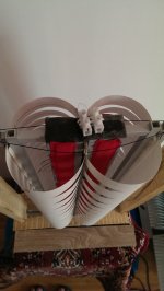
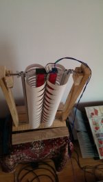
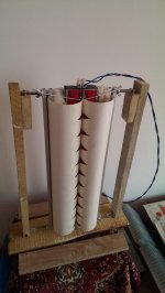
Remember my painting Wrine. Here it is in practice With the former (or coil extension made from a newspaper.
This was my surprise. So if we glue a small newspaper sheet exactly where both cilinder meet, or just add it as i did (i sticked the newspaper onto a screwdriver up and on another screwdriver down), or make the coil former bigger so that it extends to outside and will cancell the phase problem as you can see from the graph bellow.
Now i dont know what to do. Now we have literally a fullrange speaker almost flat (from measurements), BUT i'm thinking if to add this screen or not to the final ruban. Practically i think that in reality both cilinders emits same quantity of hights but because they are so close in the active portion they generate an effect like a car turbocharger or like a horn duct and sprout with hights out and the mic perceives it like a high peak..
Correct me if i'm wrong: maybe this phasing issue is only in measurements, because in reality you dont perceive this peak from 10khz to 20khz (nothing shouts). MAybe its only in the measurements.. What do you say? Should we correct this further?
Cheers
Sergiu
Attachments


All the measurements from above (from the "VS" (versus) plots and the "surprise") are made twice at 24bit@96khz.
I still think adding cuts lowers the overall mass and improves the hight frecv response, altough they do nothing till almost 20khz. I think they lower the overall active portion mass...BUT will do a ruban wit no cuts and add them after just to convince myself.
Cheers
Sergiu
I still think adding cuts lowers the overall mass and improves the hight frecv response, altough they do nothing till almost 20khz. I think they lower the overall active portion mass...BUT will do a ruban wit no cuts and add them after just to convince myself.
Cheers
Sergiu
the list refreshed again
Lets begin:
1. The magnets:
*Should they be bigger or smaller in lenght?
Smaller could be costly to acieve the same strenght, but longer could be cheaper if they achieve the same force togheter.
*should they be taller or thinner?
NA (i dont have funds for buying magnets again)
*should they be weaker or stronger?
Stronger it will ad some dB but if the cilinders are not proprely damped and designed those dB's could drive you insane because of the nasty resonances amplified. Also stronger magnets will add dollars in plus to the metal plates (more thicker,or other steel ads more money to the count).
2. Metal plates:
*A very important thing that nobody answered yet: should the plates be 2cm+1cm width so that the flux would be more concentrated or other dimensions like 2+2cm would be also good?
I use the second solution with 2+2cm width because i seen that Wrine's 3cm version bended at 3mm gap. Normally the gap is 4mm, but because i used bigger plates i got 3mm gap without bending.
*what material to use for the plates?
A37 french steel was used in the original design.
AISI 1018 was also used with succes.
Romanian equivallent is OLC15X.
We use colld rolled steel now with succes and i think that with weakened magnets like n42,n38 standard AISI1017, AISI 1018 steel can be used also.
It seems that a larger quantity of carbon diminishez the force and lesser carbon improves force further but saturates more easier. So it must be just as its needed, not too much nore too little quantity of carbon.
3. The gap:
*2,3 or 4mm?
4mm for n48 magnets its perfect, smaller gap could bend the steel..
3mm ads some dB and its the limit of suportability because you can barely keep the coil centered, and as it is the coil could bend from humidity and rub on the plates causing distorsions easily and eventually take the output trannies to their graves as they did to mine .
2mm doesnt add to much stuff, its very hard to center and keep centered the coil. Also if the coil bends only a little bit disaster will strike.
Here we have also a testimony from our colleague tubegeek974:
"PS i use neo magnets from china and 3mm gap on one loudspeaker then tryied 2MM on the other with not mutch more improvements in efficiency but lots of sorrows for centering the bobin!"
4. The coil:
*single sided or double sided? SERIES OR PARALEL? PARALELLED PHASED, OR ANTI PHASED?
NA (will test these soon)
*Copper or Al?
I found that wirewound copper its very painfull and exhausting and found allot of problems to bonding and keeping it flat..
Flexible copper pcb is a good and very fast sollution, but still too heavy. If it were for me i woul search for a coil made from flexible band that was used in the old walkmans (for the screens and push comands).
For the moment diy hand made Al coils are the winners. They are light, flat, easy to bond and have good contact with the cilinders and now we have flux to solder Al (thanks Wrine).
Wrine used here a laminated AL coil made as found in the cassette players (walkmans) with succes. (Wrine can tell us more about this if he wants)
*overhung or underhung?
NA (will test this soon)
5. The paper (what kind was tested? impregnated?speacial treated)
I use The Canson paper named "CA" at 120gr/sqm with succes. To prevent the coil from bending you need to add laqueur (allot of it) on the coil to saturate the paper, this will allso soften some dips and peaks.
Wrine tested allot of other paper till now but dont want to report.... 🙂
6. The cilinders (dims, diams, shapes)
The optimum dimensions for my 50 cm ruban are 34cm*51.5cm per sheet (cilinder) to make them round or butterfly and will give you a 4.5cm per half cilinder diameter.
Shapes: well, the round one isnt better, nor best, the shape has to be between butterfly and round because making the cills too round will make them rub on each other and atenuate hights and too butterfly will increase rigidity too much and will dampen unwanted and wanted sounds too much. So its has to bee between them.
Making the coil smaller and cilinders bigger will definetly increase lows but will decrease hights so we have to be carefull here. Wrine is testing this theory right now and could tell us more if he wants.
Wrine tested a version of ruban with a cilinder cuted down, and just one active, but didnt measure good (see the posts behind), so this way is a no go.
7. The cuts:
* First of all you have to make the cuts on the interior of the coil to lower the overall mass of the coil and for increasing the hights (for me 20pcs of 8 mm diam rounded cuts inside the coil did the magic).
* make the coil smaller with 1 cm and then centrate the coil so that you have exactly 5mm above and 5 mm bellow; this will leave the coil move more freely in the top and bottom, lower the mass and make the sound more fuller, more relaxed (subjectively speaking); this will also separate the rigid portion of the cilinders (where you have the hinges or elastics bolted) from the coil thats why i heard what i sayed "make the sound more fuller, more relaxed (subjectively speaking)".
* The exterior of the cilinders:
- i have tested rectangular and triangular cuts and the winner is definetly the triangular shape cuts;
- the bigger they are the better, BUT if you make them too long or large you will add a sweet spot in the listening area and they will decrease the integrity of the coil and could bend as i experienced on the side where the BIG cuts where made.
Tested and found out this:
The best from all of them is the CLASSIC variant with small cuts, and you cand see in the "VS" graphs why (there you will find the best measures from each).
Conclusion: the cuts have to be not higher than the 30% wich means 5.5cm hight in the active area, and no more or less than 2.2cm base lenght (when they are cutted they remain like a equilaterall triangles like in the pic with the membrane bellow) and NO MORE THAN 10 PCS. The base of the triangles has to be equal with the space between the cuts . If you do them higher then the coil tends to bend, if you make them with the base bigger (more than 2.2cm) or make more cuts than 10 not only that will make the coil bend but this will favoryse the peaks, dips and distorsions, and i think this is definetly has to do to the fact that you make the space between the cuts smaller, and this space linearise the frecv resp and dampens the peaks.
8. Suspensions
Tested yesterday:
"The elastic version has bigger dips than the hinges. The dinamics are the same (subjectivelly)and the sensitivity is a tiny bit more on the elastics but not for going this path because the dips rise higher even where you dont expect. So this aspect is solved for me. "
Elastics are a no go but i will love to use them. Today i will buy some rigid versions of elastics to test even further. But for now hinges are the winners.
If you want to go with the elastics version (because its easyier to change the membranes and recenter the coil in the future) i've tested and the finall conclusion is:
The softer the elastic is, the higher you go with the peaks and even higher with distorsion. The more tensionned you add to it, the dist goes down to almost half..
Another important aspect is that when tensionning the elastics more, the sounds comming from insyde the cuts vs between the cuts are almost the same (in a good way), except at the hights where each "covers" the other abit (the sounds from insyde and between the cuts).
Another aspect is that the ropes are a NO GO because they dont keep the coil in place at high peaks and large movements.
Thinner elastics vs thicker ones: the thinner the elastic the weaker the strenght, the higher the distortions. I use now a big elastic composed from 8 small elastics wich was the best for me..
9. Glue used
The best combo for me was first add laqueur to all the coil with the cilinder and all the other cilinder in layers till saturating the paper, then add dots of super glue on the coil like a square on the edges of the coil and dots of super glue between the round cuts inside the coil; bond the cilinders toghether fast and put a big heavy box on it and let it dry for two hours, and then 5 mins of hair drier hot air blown on it and let it cool 30min to 1hour in an opened space. (this is the method that i used)
10. Dampening
I added only medicinal cotton inside the cilinders but only between the plates and the lateralls wich bonds the paper of each cilinders together (as seen in the pics).
The cottone dampening from insyde must be insyde because the peaks that you see from my measurements (except those from 11khz to18 khz) are even higher and larger with no dampening. So the adennum of the cottone dampening insyde is very good.
Another dampening is the adenum of double adhesive tape directly onto the plates and on top of that a cottone sheet on each plate from a 100% cotton T-shirt for dampening the internall resonances (the red thing applyed onto the plates, as seen in the pics).
Also, two layers of laqueur (50% laq added from where the cilinders meet to outsyde, COMBINED WITH THE "SMALL CUTS" so that will not resonate) smoothens the overall frecv response and enlarges the sweets spot.
This is what i found today. If i think more deeper now i dont want to try to measure the ruban with a cilinder bigger and the other smaller because the smaller one will not emit hights anymore wich is a consequence for making it too rigid..
"
You can also add what you found here Wrine.
Cheers
Sergiu
Ps: I bolted with red what i still have to test. I still want to do the surprise config but will leave it at the end.
Wrine please add you findings too. Please bold with red the things that we should test, because i think i forgoted something.. I would apreciate it very much.
Last edited:
- Home
- Loudspeakers
- Planars & Exotics
- A DIY Ribbon Speaker of a different Kind