I found the problem in REW!! The problem was the distance and another calibration to do with the same loop... Now they look aprox similar. So these are the correct graphs.
I'm glad i found it. 😀
Cheers
Sergiu
I'm glad i found it. 😀
Cheers
Sergiu
Attachments
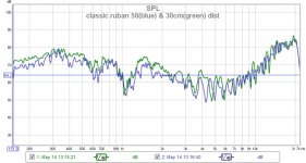
The earlyer measurements where made at aprox 1.5meters. 😎 But still REW sees that peak down and Holm sees it up. Now it seems that they display aprox the same results at that nasty peak at 20khz.. Strange thing.
Last edited:
Now we're speaking Wrine. I did it!!!😀😀😎
They are exaclty the same now (well almost). It looks that the problem was in HOLM and not in REW. I should have not trusted HOLM from the start... Anyway now its ok.
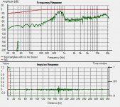
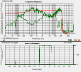
Here are all the measurements. This time HOLM measures from 6hz to 23khz. BEWARE in all these measurements i have a first order filter wich cuts in the 200-250 hz zone. To cut deeper i needed a 2nd order filter at least...
Anyway the measurements look good. I reached, with the cuts (triangular and rectangular), without deflexions in the lateralls or above a healthy frecv response from 250 to 22khz (as the inventor and Lineaum tested) with a dip of aprox -20dB down at 5khz as you cand see from the graphs from HOLM.
Wrine my friend, what do you say about the measurements now? Do you get the same dip at 5khz?
Subjectivelly speaking just with the first order filtering they sound very airy, relaxed and rounded. Very refreshing and detailled but steel needs a woofer to come join the party.
Cheers
Sergiu
They are exaclty the same now (well almost). It looks that the problem was in HOLM and not in REW. I should have not trusted HOLM from the start... Anyway now its ok.
Here are all the measurements. This time HOLM measures from 6hz to 23khz. BEWARE in all these measurements i have a first order filter wich cuts in the 200-250 hz zone. To cut deeper i needed a 2nd order filter at least...
Anyway the measurements look good. I reached, with the cuts (triangular and rectangular), without deflexions in the lateralls or above a healthy frecv response from 250 to 22khz (as the inventor and Lineaum tested) with a dip of aprox -20dB down at 5khz as you cand see from the graphs from HOLM.
Wrine my friend, what do you say about the measurements now? Do you get the same dip at 5khz?
Subjectivelly speaking just with the first order filtering they sound very airy, relaxed and rounded. Very refreshing and detailled but steel needs a woofer to come join the party.
Cheers
Sergiu
Attachments
-
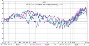 blue-classic+pink-small+green-big cuts.jpg85.4 KB · Views: 119
 -
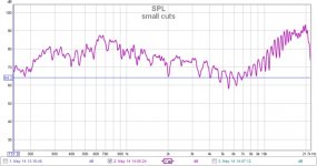 small cuts.jpg65.4 KB · Views: 355
 -
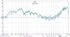 big cuts.jpg63 KB · Views: 354
 -
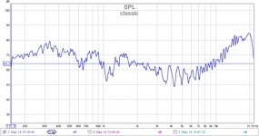 classic.jpg62.6 KB · Views: 366
 -
 classic with repaired cable.jpg239.9 KB · Views: 111
 -
 6 to 23khz big triangles.png28.2 KB · Views: 119
 -
 6 to 23khz small triangles.png28.1 KB · Views: 116
that looks more like it!!. but i dont have this dip at 5khz. one thing to note i remember they never measured it. the inventor never did as far as i know. and neither did that high end company that claims the design now.
can you activate distortion plot as well ? could be usefull information
can you activate distortion plot as well ? could be usefull information
that looks more like it!!. but i dont have this dip at 5khz. one thing to note i remember they never measured it. the inventor never did as far as i know. and neither did that high end company that claims the design now.
can you activate distortion plot as well ? could be usefull information
Hello my friend,
I told you in my listening sessions that i heard these rubans almost like my classic closed baffle with tweeter and woofer enclosure and this is the thruth, right here. I still have to test one more thing. Do you remember what i told you 10 pages back, amonth ago?
I found the best combination of cuts in membrane, and now, this week will be the final test. The last things to do: butterfly mode for the small cuts version (because this is the version that sounds best to my ears), dampening to tame those nasty dips abit (evethough i really dont perceive them in reality) and a surprise config with diferent membrane material, coils, and arrangements.... 😉 I had it in my mind for quite some time now and want to test. I will post the measurements and pics for that prototype next week after its finished. 😀
Yes, from what i seen the creator and the other company who makes them very expensive never posted the measurements, but i will. We have to bare in mind that every fullrange speaker in this world has peaks and dips and resonances and distortions because i have seen that not everithing is perfect, neither the wizer nor the surround or magnets; everithing has losses, imperfections and there have been some compromises here and there.... I atached the measuremets bellow because i want you to see that this speaker isnt perfect. There is still some more work to do but we are close here Wrine, my friend.
Do you want to know my opinion Wrine? I really think that the comercial versions of this speaker dont go higher than 15khz because they dont use the cuts nether laqueur. The membrane dampens allot of the hights and makes some huge peaks at the mids.. and then disperse them in the rest of the cilinders. At lower volumes you dont hear them too much, but when you crank up the volume abit you will hear them for shure. A concrete case was with the laqueur on the active portion, and i'm shure that you measured and heared this subtle and finesse thing. when you add laqueur more then 30% (max) onto the active portion they resonate. I didnt need to measure this, because i could hear the voices shouth and was leaving the feeling that i was in a market with allot of people there. There wasnt music anymore, there was like a bunch of guys singing and playing in a garage.. 🙂)
I really think now that the finall version is with the back cutted,like you did, and as a result i chopped the back (with the BIG cuts) as you have seen; but i preffered to chopp more in the active portion in my version and lesser on the outside of the cilinders (this will lower the overall mass but because a part of the membrane is still conected to the cilinders, they will add controll and rigidity to the back of the cilinders). The big cuts did aded hights but will not dampen soo good the mids and the mids peaks so its a no go.. They only lower the active portion mass as the center cuts did in the coil.
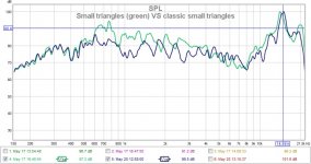
The small triangle cuts from the front did improved the hights and tamed some peaks but i think that this is only a consequence of the cutted back. As we have seen in the "classic" plots it doesnt measure the same and i think that its because the classic dont have the back cutted like the small cuts. Bare in mind that the mass removed with the rectangular cuts in the "classic" is the same as the small triangles. The only thing here to test is to chepp the back of the "classic" to see if the rectanmgular cuts are better than the traingles.
So a good combination (or maybe the best) is a combination of both (big cuts in the back and smaller ones in the front)..
Subjectivelly speaking at the listening tests, i didnt perceive any duck voice, shouts, didnt hear any buzzez, or anything like that. These dips are only in the measurements.. To my ears these speakers (with the cuts and moifications that i did) sounds different (in a good way), cleaner, more detailed and and very profound. They rise the hair on you back when you hear the singers lips clipings because theyr mouth is dry; the drums sound as the real thing (i'm not kiddind!!), and the violin....well its like singing in you room... You cand really feel the music now, it really transmits emotions not sound. This is what good music should sound; cant wait to pair them with the 15" PA woofers. I have to wait a little till then but i can smell it, the succes; we are close..
I havent fell in love with these speakers yet. I told you only my subjective impressions from the listenin tests. I will tell you more after the bass speakers will come in the equation.
Anyway, i have found, from this testing trial, that the only ones who tested and tell the thruth, and measured and really invested time, money, materials and human labour, are the guys from Lineaum. Some things from their patents are very usefull BUT as you have seen, Wrine, there is some c***y s***t and false things too there as i tested. I dont know why, maybe they use different materials, or protect some manufacturing secrets, i dont know.
I will add this week what i found to the list that we made earlier my friend and maybe others will join with their discoveries two..
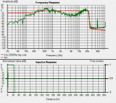
Some here are the distort measures. Accidentally i erased the classic plot from HOLM yesterday, but have them in the REW program. Unfortunatelly i dont understant how to interpret the distort from REW because when you move the blue cursor on the graph the REW shows on each peak in each harmonic the amplitude of the ditortion. I will attach the program files too.
These measurements where made from 50CM distance.
This was done like this because i had a real BIG problem with my first measurements. The problem was the distance and the volume and i think that this has to do with the mic and the dispersion of the sound in the measuring room and i'm glad that i figured it out. Another problem i had was with some bad joints wich where not proprely shielded and the mic and amp was picking allot of noise....
Attachments
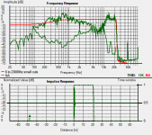
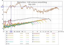
something seems wrong still. the THD for instance is a bit high, 4 and higher % and going up , compared to down normally. the line looks a bit to smooth to. i think you got some major distortion coming from somewhere and the peaks you see down low are the ones that pass the distortion that is already there without the speaker adding anything. you can see verry profound differences in the FR but none in the distortion, usually peaks and nulls go hand in hand with increasing distortion in a null for instance. while your FR go up and down distortion curve stays flat and slightly rising. my best bet is something going wrong in the mic amplifier, or cabling or any other form of bad connection.
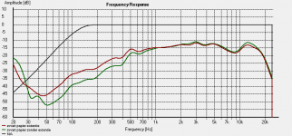
I did a test as well, i added 8 cm of extra paper tot he cylinders. just a crude piece i glued on the left and right cylinder to see what would happen especially to the low end, to see if it will yield anything to make them larger. And for most, larger then the actual coill length. so for instance 20 cm coil with 30 cm cylinders.
result looks like it helps the low and pretty well.
Green = normal
Red = with 8 cm of extra paper on the cylinders.
almost 6 dB for free down low. so i know what i will do when i got some free time 🙂 get me some bigger metal to make a taller version. at first i will try to use the same amount of magnets i used for this version. so i can compare it. (although i dont know what happens to the magnetic field when the metal strip is twice as long) might need to try and sim that 🙂
EDIT: **** cant sim that 🙁 Femm is always a top view, i can imagine making the metal bar long without adding more magnets would result in the field spreading. so there will be magnetic field in places i dont need it. but i cant simulate it 🙁
Attachments
Last edited:
Hello my friend,
You are right. I thought about this all the night. So today i testedeverithing again and found:
-i had a node with a switch on the amp wires (with this i could switch of a chanel to hear the other) who wasnt isolated so well and was traveling beneath some 220v wires and was inducing a small amount of noise to the ruban..
-the psu filtering was a cap multiplier with no regulation so i switched to a regulated low noise psu and crc filtering and star ground. Dont know why but now with the reg psu the graph is as you said, lowers down till 10khz. The dominant harmonics are 2and the 3. I thoungh that was a a cable or program and made 20 measurements till figured it out. Just imagine that i made the psu in the afternoon when the 220v was 216v and when i measure in the morning was 218v so it was sufficient to rise the Ual from 12v to 14v and to 10,5v at night (enought to distort). .Will post the graphs when ariving home. Now all is ok. My graphs looks similar as yours especially in the 7-9khz region. 🙂
Your graphs looks smoother now. What did you use 12dB smoothing?
I have to advise you not to exagerate with going bigger with the cilinder surface vs coil, because i think it will increase lows but i see that it also dampens abit the hights too. You have to be carefull here.
I want to share my founds from today too: those strange and smoother plots was like that because of THE RUBBING of the coil TO THE PLATES. Yes my friend, the classic version wasnt saturated with laqueur on the inside of the cilinders so it bended nasty...thats why it looked smoother. This rubing soft like touching the membrane softly with a finger and softening the dips.. On the newer version of ruban (with bigger cuts) it bended only on a portion on top, in two spots. These spots where clearly not laqueured (seen it with my eyes).
On the newer vers the case was resolved. Now i have some bigger dips, and in rest remains the same. The dist graphs now looks as you said. 🙂
With this ocassion i tested the bigger hinges vs elastics. The conclusion is:
-when you blow air into the elastics version and see how freely it moves, you say to yourself "wow this has to be very sensitive and have allots of dinamics" but its not. The elastic version has bigger dips than the hinges. The dinamics are the same (subjectivelly)and the sensitivity is a tiny bit more on the elastics but not for going this path because the dips higher even where you dont espect. So this aspect is solved for me.
Another thing is that bigger cuts creates soft spot in the listening room wich is not desirable, and because the cuts are deeper in the cilinders they dont have much controll in keeping the coil centered in the gap (in the back) and tends to bend..
Will post pics soon.
Cheers
Sergiu
Here are the graphs. As you can see in the pics, the diff between the new and old psu and diff between elastics and hinges.
Attachments
-
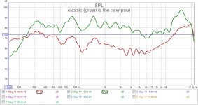 classic (green is the new psu).jpg75.4 KB · Views: 120
 -
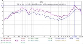 blue big cuts & pink big cuts with new psu and elastics.jpg78.8 KB · Views: 116
 -
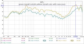 green (small cuts)& yellow (small cuts with new psu).jpg76.7 KB · Views: 106
 -
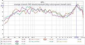 orange (classic NO elastic)+purple (big cuts)+green (small cuts).jpg84.7 KB · Views: 112
 -
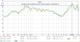 small cuts (yellow-new psu)+green (elastics).jpg73.5 KB · Views: 104
the truth is even more in the distortion measurements.
But looking more like real life already. that being said, it also let us see the major issues. having peaks and nulls of 10 dB.
About my measurements above. they where heavily smoothed 24db oct only for showing the differences. also i used super glue heavy on this test version, since i still wondered what it would do. and it only cripples the high end 🙂 so i skip that step next time.
As for rubber bands or the triangled cuts.
one thing i i wanted to pont out is that the place where the coil makes the turn is where the movement wont be forward backwards but up and down. this and because of low frequency's can get the coil out of the gap with ease i recon we need far more heavy suspension. maybe in the form of a spider? over the entire length.
when using rubber bands they need to be tight, not sloppy like i would think they should be , since this will allow up and down movement, and allows it to get out of the gap when resonance is hit. i might need to find stronger rubber bands. to try.
btw i think the triangled hinges dampens the peaks a bit since it is not allowed to move much there, just like adding weight (like these rubber strips i used so often) but it could potential be a source of resonances as well, and limits excursion from a few mm to les then one mm. i would like to have 2 mm of motion to be honest.
the truth is even more in the distortion measurements.
But looking more like real life already. that being said, it also let us see the major issues. having peaks and nulls of 10 dB.
About my measurements above. they where heavily smoothed 24db oct only for showing the differences. also i used super glue heavy on this test version, since i still wondered what it would do. and it only cripples the high end 🙂 so i skip that step next time.
As for rubber bands or the triangled cuts.
one thing i i wanted to pont out is that the place where the coil makes the turn is where the movement wont be forward backwards but up and down. this and because of low frequency's can get the coil out of the gap with ease i recon we need far more heavy suspension. maybe in the form of a spider? over the entire length.
when using rubber bands they need to be tight, not sloppy like i would think they should be , since this will allow up and down movement, and allows it to get out of the gap when resonance is hit. i might need to find stronger rubber bands. to try.
btw i think the triangled hinges dampens the peaks a bit since it is not allowed to move much there, just like adding weight (like these rubber strips i used so often) but it could potential be a source of resonances as well, and limits excursion from a few mm to les then one mm. i would like to have 2 mm of motion to be honest.
i thought about pulling them really hard, and put them almost above where they are connected to the cylinder, so there is a decent pulling force vertical but still be able to move horizontal
The list refreshed
"Hello again my friend. Thanks for the list. I apreciate it.
I also have a bunch of questions to add too. Tomorrow morning i will put down my thoughts too. I hope that we can make a list from our questions with what to do, and not to, what has been tested and what not. I think that this way we can know in what direction to go and what to search for. What do you say?
I think that we are doing allot of things (tests) at the same time without having a precise direction, like some chapters to solve or to be solved. You can modify it as you wish and add what you found. Also add questions too.
Lets begin:
1. The magnets:
*Should they be bigger or smaller in lenght?
Smaller could be costly to acieve the same strenght, but longer could be cheaper if they achieve the same force togheter.
*should they be taller or thinner?
NA (i dont have funds for buying magnets again)
*should they be weaker or stronger?
Stronger it will ad some dB but if the cilinders are not proprely damped and designed those dB's could drive you insane because of the nasty resonances amplified. Also stronger magnets will add dollars in plus to the metal plates (more thicker,or other steel ads more money to the count).
2. Metal plates:
*A very important thing that nobody answered yet: should the plates be 2cm+1cm width so that the flux would be more concentrated or other dimensions like 2+2cm would be also good?
I use the second solution with 2+2cm width because i seen that Wrine's 3cm version bended at 3mm gap. Normally the gap is 4mm, but because i used bigger plates i got 3mm gap without bending.
*what material to use for the plates?
A37 french steel was used in the original design.
AISI 1018 was also used with succes.
Romanian equivallent is OLC15X.
We use colld rolled steel now with succes and i think that with weakened magnets like n42,n38 standard AISI1017, AISI 1018 steel can be used also.
It seems that a larger quantity of carbon diminishez the force and lesser carbon improves force further but saturates more easier. So it must be just as its needed, not too much nore too little quantity of carbon.
3. The gap:
*2,3 or 4mm?
4mm for n48 magnets its perfect, smaller gap could bend the steel..
3mm ads some dB and its the limit of suportability because you can barely keep the coil centered, and as it is the coil could bend from humidity and rub on the plates causing distorsions easily and eventually take the output trannies to their graves as they did to mine .
2mm doesnt add to much stuff, its very hard to center and keep centered the coil. Also if the coil bends only a little bit disaster will strike.
Here we have also a testimony from our colleague tubegeek974:
"PS i use neo magnets from china and 3mm gap on one loudspeaker then tryied 2MM on the other with not mutch more improvements in efficiency but lots of sorrows for centering the bobin!"
4. The coil:
*single sided or double sided? SERIES OR PARALEL? PARALELLED PHASED, OR ANTI PHASED?
NA (will test these soon)
*Copper or Al?
I found that wirewound copper its very painfull and exhausting and found allot of problems to bonding and keeping it flat..
Flexible copper pcb is a good and very fast sollution, but still too heavy. If it were for me i woul search for a coil made from flexible band that was used in the old walkmans (for the screens and push comands).
For the moment diy hand made Al coils are the winners. They are light, flat, easy to bond and have good contact with the cilinders and now we have flux to solder Al (thanks Wrine).
Wrine used here a laminated AL coil made as found in the cassette players (walkmans) with succes. (Wrine can tell us more about this if he wants)
*overhung or underhung?
NA (will test this soon)
5. The paper (what kind was tested? impregnated?speacial treated)
I use The Canson paper named "CA" at 120gr/sqm with succes. To prevent the coil from bending you need to add laqueur (allot of it) on the coil to saturate the paper, this will allso soften some dips and peaks.
What paper did you test Wrine, and what can you tell uis about them?
6. The cilinders (dims, diams, shapes)
The optimum dimensions for my 50 cm ruban are 34cm*51.5cm per sheet (cilinder) to make them round or butterfly and will give you a 4.5cm per half cilinder diameter.
Shapes: well, the round one isnt better, nor best, the shape has to be between butterfly and round because making the cills too round will make them rub on each other and too butterfly will increase rigidity too much and will dampen unwanted and wanted sounds too much. So its has to bee between them.
Making the coil smaller and cilinders bigger will definetly increase lows but will decrease hights so we have to be carefull here. Wrine is testing this thery right now and could tell us more if he wants.
7. The cuts:
* First of all you have to make the cuts on the interior of the coil to lower the overall mass of the coil and for increasing the hights (for me 20pcs of 8 mm diam rounded cuts inside the coil did the magic).
* make the coil smaller with 1 cm and then centrate the coil so that you have exactly 5mm above and 5 mm bellow; this will leave the coil move more freely in the top and bottom, lower the mass and make the sound more fuller, more relaxed (subjectively speaking); this will also separate the rigid portion of the cilinders (where you have the hinges or elastics bolted) from the coil thats why i heard what i sayed "make the sound more fuller, more relaxed (subjectively speaking)".
* The exterior of the cilinders:
- i have tested rectangular and triangular cuts and the winner is definetly the triangular shape cuts;
- the bigger they are the better, BUT if you make them too long or large you will add a sweet spot in the listening area and they will decrease the integrity of the coil and could bend as i experienced on the side where the BIG cuts where made.
Will have to test further here to fin the optimum dims and how large and long they should be.
8. Suspensions
Tested yesterday:
"The elastic version has bigger dips than the hinges. The dinamics are the same (subjectivelly)and the sensitivity is a tiny bit more on the elastics but not for going this path because the dips rise higher even where you dont expect. So this aspect is solved for me. "
Elastics are a no go but i will love to use them. Today i will buy some rigid versions of elastics to test even further. But for now hinges are the winners.
9. Glue used
The best combo for me was first add laqueur to all the coil with the cilinder and all the other cilinder in layers till saturating the paper, then add dots of super glue on the coil like a square on the edges of the coil and dots of super glue between the round cuts inside the coil; bond the cilinders toghether fast and put a big heavy box on it and let it dry for two hours, and then 5 mins of hair drier hot air blown on it and let it cool 30min to 1hour in an opened space. (this is the method that i used)
10. Dampening
I added only medicinal cotton inside the cilinders but only between the plates and the lateralls wich bonds the paper of each cilinders together (as seen in the pics).
Another dampening is the adenum of double adhesive tape directly onto the plates and on top of that a cottone sheet on each plate from a 100% cotton T-shirt for dampening the internall resonances (the red thing applyed onto the plates, as seen in the pics).
"
You can also add what you foun here Wrine.
Cheers
Sergiu
Ps: I bolted with red what i still have to test. I still want to do the surprise config but will leave it at the end.
Wrine please add you findings too. Please bold with red the things that we should test, because i think i forgoted something.. I would apreciate it very much.
well i made a 30 cm version with the 1 mm magnets... and ust before i wanted to sweep the smaller one as for comparison. i noticed the huge dip aroun 9khz, and later in the newer version to.... as it seems the it is still the phasing issue of having 2 cylinders producing high freq. a dome never exceeds 18 mm in depth because it will result in pahsing issues. 🙁 and same for this ruba. i aparantly measured slightly of axis last time when it was sort of flat. but right in the middle it is certainly not. it creates a dip at 9khz a pretty wide one to. sort of like your dip although be it slightly higher in the frequency domain... im not sure yet what to do about it, i wondered what would hapen if you damp one of the cylinders from the coil so it only transfers lower ferquency's..... not sure if it will work and hurt the rest to.
when you move your head side ways you will notice high end gets better until you are not looking at the where the cylinder starts and the other cylinder is getting in the way in the line of sight.
damned..... i first want them to have a smooth high end before making them bigger. i want a a flat upper response 🙂 or at least flater.
So its the same as mine.
Let me tell wat hapened yesterday and today. The musician friend of mine came and listen to the rubans. We both agreed that the at the end of the day the elastics sounds more opened and the hinges sounds like restrained... Really strange thing. We loved the elastics but could not love the hinges altought they measure better than the hinges. The voices are abit more round at the elastics and they seem to be more revealing. Really strange thing....
Anyway i converted both rubans to elastics and cannot come back to hinges till next versions because i cutted the hinges off. Another aspect is that the elastics are easyer to center and swap for mods then hinges, for tests.
I did some cuts in the classic version and its seems to sound better than the BIG+Small cuts vers; will measure and post my findings tomorrow.
Cheers
Sergiu
nice, but the enormous dip still remains 🙁 i already said it and convinced myself it worked in some magical way.... 🙁 and then i woke up ... the structure itself seems to be at fail here no mater what paper used 🙁 aaah well i keep on playing 🙂
Hello my friend,
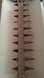
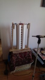
Here is a new thing that i did yesterday. Modifying the classic: tunning with cuts (as you can see from the pic with the membrane on the syde with 30% laqueur i have small cuts and on the side with 50% laqueur i have the bigger cuts). The cuts are made for now only in the active region of the cilinder and no more. Here are some pics on how it looks and measures.
As you can see from the measurements, they where with filtering till now. This is my first measurement with no filter only on one side (the one with 30% laqueur).
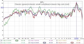
The strangest thing is that (as you can see in the pics) BIG cuts in the classic version did somehow smoothen the 8khz hole, but has a 1khz whole, and small cuts have a hole at 8khz, have abit more dB between 16khz to 20khz, but have a whole at 1khz.
Today i want to see why and how ??
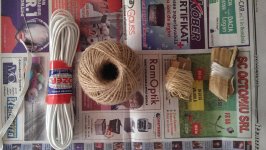
And test the new elastics and robes. In the pic with elastics i have from left to right: thin elastics, thick elastics, jute twine rope, thin nylon rope and very thin nylon string (like the one used at phishing).
Cheers
Sergiu
Here is a new thing that i did yesterday. Modifying the classic: tunning with cuts (as you can see from the pic with the membrane on the syde with 30% laqueur i have small cuts and on the side with 50% laqueur i have the bigger cuts). The cuts are made for now only in the active region of the cilinder and no more. Here are some pics on how it looks and measures.
As you can see from the measurements, they where with filtering till now. This is my first measurement with no filter only on one side (the one with 30% laqueur).
The strangest thing is that (as you can see in the pics) BIG cuts in the classic version did somehow smoothen the 8khz hole, but has a 1khz whole, and small cuts have a hole at 8khz, have abit more dB between 16khz to 20khz, but have a whole at 1khz.
Today i want to see why and how ??
And test the new elastics and robes. In the pic with elastics i have from left to right: thin elastics, thick elastics, jute twine rope, thin nylon rope and very thin nylon string (like the one used at phishing).
Cheers
Sergiu
Attachments
-
 classic big cuts 50% laquered.jpg71 KB · Views: 278
 -
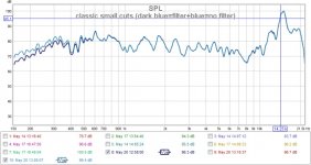 classic small cuts (dark blue=filter+blue=no filter).jpg75.8 KB · Views: 270
 -
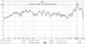 classic small cuts 30%laquered.jpg70.1 KB · Views: 256
 -
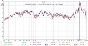 classic with cuts (blue SMALL+ red BIG).jpg78.1 KB · Views: 273
 -
 IMAG0129.jpg850.5 KB · Views: 298
 -
 IMAG0130.jpg904.8 KB · Views: 207
 -
 IMAG0132.jpg549.1 KB · Views: 193
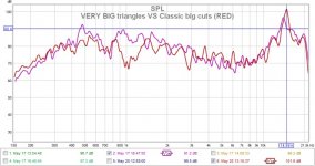
Till it dries (i laquered the 30% face up to 50%). Here are some comparisons between the almost chopped back (BIG and SMALL triangles) and "Classic" style.. The classic "classic" with rectangular cuts have been measured only on the 30% laquered face bcause that was better in measuremts. 😀
Attachments
Last edited:
The laqueur has hardened (its very fast).
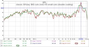
You wouldnt believe what happened Wrine. Adding 50% (half cilinders filled with laq on one side ) in two coats of laquer on the small cuts ("classic" vers with 30% laq) smooths the holes, the overall frecv resp and the peak neak 20khz. Very cool. 😎
You wouldnt believe what happened Wrine. Adding 50% (half cilinders filled with laq on one side ) in two coats of laquer on the small cuts ("classic" vers with 30% laq) smooths the holes, the overall frecv resp and the peak neak 20khz. Very cool. 😎
Attachments

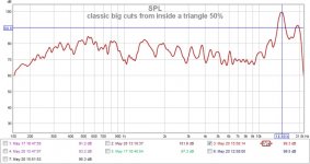
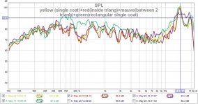
I also aded two layer on the big cuts in the classic vers.Here we can see that in the classic big cuts there are very noaticeble differences between the mic positioned on the inside the cuts and between the cuts. The smoothest thing (except for a dip at 1khz) is between the cuts...
Attachments
-
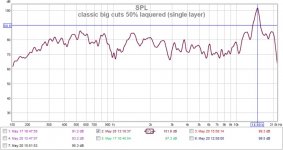 classic big cuts 50% laquered (single layer).jpg71.5 KB · Views: 97
 -
 classic big cuts between two triangles 50%.jpg71.4 KB · Views: 85
 -
 classic big cuts from inside a triangle 50%.jpg73.2 KB · Views: 85
 -
 yellow (single coat)+red(inside triang)+mauve(between 2 triang)+green(rectangular single coat).jpg90.5 KB · Views: 92
The laqueur has hardened (its very fast).
You wouldnt believe what happened Wrine. Adding 50% (half cilinders filled with laq on one side ) in two coats of laquer on the small cuts ("classic" vers with 30% laq) smooths the holes, the overall frecv resp and the peak neak 20khz. Very cool. 😎
On the BIG cuts from this post seemes that the mic was positioned between two cuts.
- Home
- Loudspeakers
- Planars & Exotics
- A DIY Ribbon Speaker of a different Kind