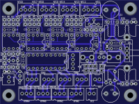
SMPS 😉... today got some lasered parts for my 4 channel variant of SA2015 ...
Your plan is a 4 channel amplifier.Yes! 1200W max. 20 Hz save ...
Is this SMPS enough for this?
Can you post the type of SMPS?
Has enough power: https://www.hypexshop.com/DetailServlet?detailID=6172Your plan is a 4 channel amplifier.
Is this SMPS enough for this?
Can you post the type of SMPS?

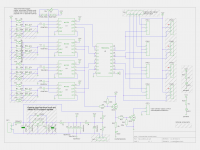
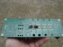
SA2015 housekeeping circuits - fan controller board
... as SA2015 is active cooled we need a fan controller.
Completely untested! You've been warned ... 😉
BR, Toni
... as SA2015 is active cooled we need a fan controller.
Completely untested! You've been warned ... 😉
BR, Toni
Attachments
Last edited:
I've still got to finish SA2014 without blowing it and myself up! 😱
I've build 8 SA2014 boards - none of them has made any problems. If you run a safety startup procedure similar to SA2015 (example in post #1553)... it is very likely that no part gets damaged even in case of an assembling error. 😉
... as SA2015 is active cooled we need a fan controller.
Completely untested! You've been warned ... 😉
BR, Toni
I use th Crest Audio solution. It's continously controlled speed fan, with linear regulation. Very simple solution, even very good working.
Sajti
Thx for info - schematic available?I use th Crest Audio solution. It's continously controlled speed fan, with linear regulation. Very simple solution, even very good working.
Sajti
Attached.
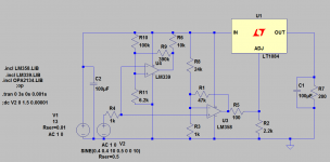
LM35 working as a temperature sensor(V2), LM358 acting as error amplifier, and LT108x produce the output voltage. LM339 makes the high temperature shut down.
The picture attached, was planned to working from+13V, and feed 12V fan, this is why it use LDO voltage regulator. LM317 is suitable if the power supply higher than 15V. (R8 must be change, for different supply voltage!)
I can attach the simulation results too.
Sajti
Attachments
...
Sajti
Hmmm. This is a nice analog circuit but this doesn't tear me from the chair. No PWM - many fan's have problems with dc regulated power. The mic502 (which uses ~ 20Hz PWM - mostly unhear-able) has a special startup procedure for starved fans. Normal analog circuits are not able to reanimate stopped fans. My (of course currently untested) schematic uses 5 IC's to control 4 independent fan's with up to 8 temperature checkpoints.
The analog solution needs 4 IC's to control 1 Fan with 1 temp checkpoint ...
Have fun, Toni
please moderator remove all the annoying and noisy comments of this lazy lazy cat. thx.

thx moderator!please moderator remove all the annoying and noisy comments of this lazy lazy cat. thx.
Hmmm. This is a nice analog circuit but this doesn't tear me from the chair.
Maybe not but it was not the main goal of this circuit 🙂
No PWM - many fan's have problems with dc regulated power. The mic502 (which uses ~ 20Hz PWM - mostly unhear-able) has a special startup procedure for starved fans. Normal analog circuits are not able to reanimate stopped fans.
I never found stopped fan using this circuit. It was build many time using different parts, including the industrial Papst fan, or the crappy 1Euro chineese too. I found, that all of them will start if I can give them enough current. The only problem was, if we used series resistor to reduce the speed of them. But the usual regulators, are able to give the necessary current. My last version use 1117 LDO (price is 0.2Euro/pc) for 230mA fan.
My (of course currently untested) schematic uses 5 IC's to control 4 independent fan's with up to 8 temperature checkpoints.
The analog solution needs 4 IC's to control 1 Fan with 1 temp checkpoint ...
This schematic is just a part of a full protection. Not optimized for many sensing points, and the ICs was defined by the other parts of the housekeeping (LM339 acting as turn on delay, signal present, and clip LED driver as well).
But You can simply add more sensing points, using quad version of LM358. Using many sensor points to drive single fan is just replace R5 with simple diode-diode logic. For simple solution You can use the other half of the LM358 for the high temperature alarm. You have many possibilities to optimize the circuit for Your purposes...
Another advantage, that all ICs are very cheap, and available everywhere.
Sajti
Last edited:
- Home
- Amplifiers
- Solid State
- 2stageEF high performance class AB power amp / 200W8R / 400W4R