Quasi has Threads for Quasi complementary amplifiers.
They were very popular at that time. We still see a few references to his range of excellent Quasi amplifiers, particularly the big Nchannel types.
They were very popular at that time. We still see a few references to his range of excellent Quasi amplifiers, particularly the big Nchannel types.
One of my oldest DIY amplifiers have had quasi complementary - big surprise - 2N3055 output stages. This amplifier has been build 1980 ... and was till 2010 in a good working condition (and is now part of my private electronic museum)
For which N-Channel MOSFET types do you want a high power quasi complementary design?
For which N-Channel MOSFET types do you want a high power quasi complementary design?
...
In reality, any of your designs are more than good enough.
...
Thanks! Thanks also to the many diyaudio members which helped to improve the amplifier circuits! 🙂
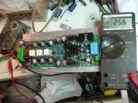
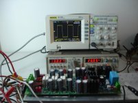
First time singing without bad surprises.
Tested at +/-23V.
Offset=25mV Without inp.connection to star gnd
Offset=0mV WHEN INP GND CONNECTED TO STAR GND.
Good warm dynamic sound!
Nice work Toni!
Highly recommended!
Tested at +/-23V.
Offset=25mV Without inp.connection to star gnd
Offset=0mV WHEN INP GND CONNECTED TO STAR GND.
Good warm dynamic sound!
Nice work Toni!
Highly recommended!
Attachments


Last edited:
First time singing without bad surprises.
Tested at +/-23V.
Offset=25mV Without inp.connection to star gnd
Offset=0mV WHEN INP GND CONNECTED TO STAR GND.
Good warm dynamic sound!
Nice work Toni!
Highly recommended!
My congratulations! 🙂
Bias checked when cold / hot? Should be no big difference...
BR, Toni
SA 2015
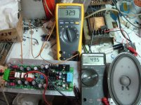
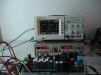
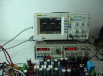
Thanks Toni ,bias between tp1,tp3=49.5mV when tempr.is 32.9 C.(Picture No3)
If this will be useful for someone.
To be continued after test bed cleaning😀
Thanks Toni ,bias between tp1,tp3=49.5mV when tempr.is 32.9 C.(Picture No3)
If this will be useful for someone.
To be continued after test bed cleaning😀
Attachments
Last edited:
For which N-Channel MOSFET types do you want a high power quasi complementary design?
Hi Toni,
I actually thought about starting out with IRFP240, since I have some of those.
Best,
Mogens


SA2015
The rest.
To be continued.
The rest.
To be continued.
Attachments
Last edited:
Your results look very good! 🙂
Try also a small signal (8Vpp) 200kHz square wave too to be sure you get the same results as shown here. (This output level is save for your zobels.)
BR, Toni
Try also a small signal (8Vpp) 200kHz square wave too to be sure you get the same results as shown here. (This output level is save for your zobels.)
BR, Toni
Ok Toni,i love to smell zobel resistors🙂Your results look very good! 🙂
Try also a small signal (8Vpp) 200kHz square wave too to be sure you get the same results as shown here. (This output level is save for your zobels.)
BR, Toni
I have do this but i haven't photo....don't worry coming soon!
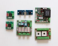
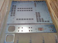
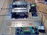
I feel very privileged to have Toni help me build his very impressive SA2014 200W/8R power amplifier. Some pics of things so far. (I am a slow builder and this is my first amp build.)
1. Heat spreaders for OPS
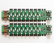
2+3. IPS-VAS
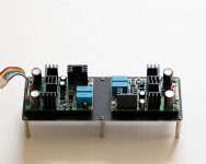
4+5: Bias/OPS stage
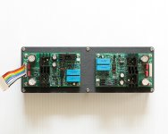
6. My Aux PSUs
7+8: Main PSUs
9. 2 x 600VA toroids
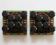
10. Output relays and zobels, standby control and USB admin, in-rush control, main controller for relays etc, dual star ground
Now that I have the heat spreaders I can install the thermal monitoring NTC, mount the Bias/OPS and begin some testing.
1. Heat spreaders for OPS
2+3. IPS-VAS
4+5: Bias/OPS stage
6. My Aux PSUs
7+8: Main PSUs
9. 2 x 600VA toroids
10. Output relays and zobels, standby control and USB admin, in-rush control, main controller for relays etc, dual star ground
Now that I have the heat spreaders I can install the thermal monitoring NTC, mount the Bias/OPS and begin some testing.
Attachments
-
 Admin.jpg177 KB · Views: 461
 -
 Toroids.jpg180.3 KB · Views: 425
 -
 Main PSUs-2.jpg126.2 KB · Views: 396
 -
 Main PSUs.jpg153.3 KB · Views: 417
 -
 Aux PSUs.jpg156.9 KB · Views: 438
 -
 BIAS-OPS-2.jpg145.1 KB · Views: 756
 -
 BIAS-OPS.jpg253.3 KB · Views: 762
 -
 IPS-VAS-2.jpg127.6 KB · Views: 737
 -
 IPS-VAS.jpg144.1 KB · Views: 752
 -
 Heat Spreaders.jpg134.5 KB · Views: 773
I feel very privileged to have Toni help me build his very impressive SA2014 200W/8R power amplifier. Some pics of things so far. (I am a slow builder and this is my first amp build.)
...
That looks very impressible too! Ultra professional for a first DIY amplifier.
I feel honored that Thimios, you and maybe others are building these amplifiers...
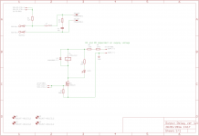
Maybe you want to show us schematics (and gerbers?) of the two additional boards you have designed? Opamp powersupply and the speaker output relais pcb's?
Have fun, Toni
SA2015
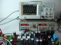
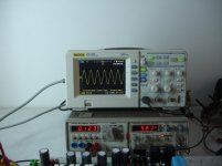
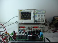
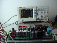
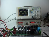
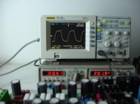
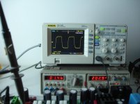
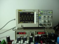
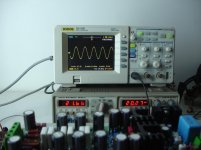
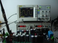
1 Just before clipping 23V RMS/6R=88W RMS
2 Clipping.
3 Rise time
4 200KHz behind R.L
5 200KHz after R.L
6 400KHz behind R.L
7 100KHz behind R.L
1 Just before clipping 23V RMS/6R=88W RMS
2 Clipping.
3 Rise time
4 200KHz behind R.L
5 200KHz after R.L
6 400KHz behind R.L
7 100KHz behind R.L
Attachments


Last edited:
200kHz looks identical to my measured values. Very good! You can expect best performance! 🙂
Even 20kHz clipping is identical and nearly no sticking visible.
Have fun, Toni
Even 20kHz clipping is identical and nearly no sticking visible.
Have fun, Toni
Thanks Toni...for all🙂🙂200kHz looks identical to my measured values. Very good! You can expect best performance! 🙂
Even 20kHz clipping is identical and nearly no sticking visible.
Have fun, Toni
You have make a very good job here.🙂
I'm glad to see good, high class DIY amplifiers such yours in this forum.
Best Regards.
Thimios
That looks very impressible too! Ultra professional for a first DIY amplifier.
I feel honored that Thimios, you and maybe others are building these amplifiers...
Maybe you want to show us schematics (and gerbers?) of the two additional boards you have designed? Opamp powersupply and the speaker output relais pcb's?
Have fun, Toni
Thanks. I just do what the Master says... 😉 IPS/VAS and BIAS/OPS are now ready for testing.
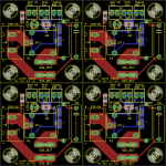
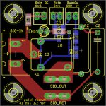
Here is the simple output relay board. Gerbers for 2x2 panel attached also. I have spare boards if anyone is interested.
In hindsight, perhaps the Zobel capacitor and resistor need not have been good, large through-hole parts - only unwanted frequencies pass through them - and so I could have deviated from Toni's BoM part recommendations in favour of SMD? That with just two mounting holes would have allowed an even smaller board. Currently it is 4x4cm.
Aux PSU to follow.
Attachments
Nice!I feel very privileged to have Toni help me build his very impressive SA2014 200W/8R power amplifier. Some pics of things so far. (I am a slow builder and this is my first amp build.)
1. Heat spreaders for OPS
2+3. IPS-VAS
4+5: Bias/OPS stage
6. My Aux PSUs
7+8: Main PSUs
9. 2 x 600VA toroids
10. Output relays and zobels, standby control and USB admin, in-rush control, main controller for relays etc, dual star ground
Now that I have the heat spreaders I can install the thermal monitoring NTC, mount the Bias/OPS and begin some testing.
This will be a Titan!
- Home
- Amplifiers
- Solid State
- 2stageEF high performance class AB power amp / 200W8R / 400W4R