Have a look at the scope photos in post #68 of this thread. The horizontal sweep rate is 2 microseconds per division and that's about the slowest he could go while still able to view the details of the oscillatory peaks and troughs.
It appears that your $28 scope kit cannot sweep faster than 10 microseconds per division, which means it is a factor of 5 too slow for member dimkasta's transformer. Who knows, your transformers might oscillate at extremely low frequencies and your scope might show these oscillations perfectly well. But keep in mind that there do exist transformers which oscillate at high frequencies and which therefore require finer granularity on the horizontal axis than this kit provides. We know it's true, we've seen the traces.
Another piece of data that may be helpful is: the two transformers which I used for soft recovery diode testing in this Linear Audio article, oscillated at a frequency where the best scope setting was 5 microseconds per division. Again, I have no idea whether your transformers will oscillate faster, or slower, than mine. I'm just telling you that all the scope pictures in that article used 5 microseconds per division.
On the other hand, building your own oscilloscope from a kit seems like a delightful pastime, and a lot of fun for not much money. So, why not try it out and have some laughs? If the finished kit also happens to be useful for snubbing a few transformers, that's an extra and unexpected bonus!
Circuit theorists and polymaths reading this thread, may wish to offer their suggestions about additional things a person might consider doing, to get reasonable results with a scope limited to 10usec/div or slower. Both the obvious ones and the subtle.
Last edited:
We need a new thread? Best scope for those on a tight budget?cheers, it was from Farnell BITSCOPE MICRO - BITSCOPE - OSCILLOSCOPE, 2+6CH, 20MHZ, 40MSPS | Farnell element14
Hantek 6022BE PC-Based USB Digital Storag Oscilloscope 2 Channels 20MHz 48MSa/s - US$68.99
Regards,
Dan
It may work, but I think you would be better using an old analogue oscilloscope.
>=20MHz and <=5mV/div
>=20MHz and <=5mV/div
Cheapomodo's output signal is several volts and you can make it a dozen volts if you wish, simply by connecting it to an 18V power supply such as two 9V transistor radio batteries in series.
diyAudio member funk1980's cheapomodo (post #15 of this thread) gave a 7 volt output signal. His transformer oscillated slowly and his photo uses 10 usec/div horizontal sweep.
Member oliphant's cheapomodo (post #42) gave a 2 volt output signal.
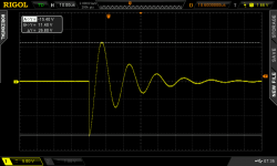
Just now I dragged out my stripboard (aka "veroboard") cheapomodo and took a scope photo with it: Figure 1 below. As you can see the vertical scale is 5 volts/div and the horizontal scale is 10 microsec/div.
The signal amplitude was quite large: -15 volts (cursor A) to +11 volts (cursor B). More than ten thousand millivolts.
You don't need an oscilloscope with 5 millivolts/division of vertical gain, to use Cheapomodo. There may be other reasons to want high sensitivity but Cheapomodo is not one of them.
And I remain hopeful and confident that in just a few days the polymaths and circuit theorists of diyAudio will post messages here, telling you how to get good performing snubbers that you can measure perfectly well, on a cheap oscilloscope that won't sweep any faster than 10 microseconds/division. Both the obvious way and the subtle way.
_
diyAudio member funk1980's cheapomodo (post #15 of this thread) gave a 7 volt output signal. His transformer oscillated slowly and his photo uses 10 usec/div horizontal sweep.
Member oliphant's cheapomodo (post #42) gave a 2 volt output signal.
Just now I dragged out my stripboard (aka "veroboard") cheapomodo and took a scope photo with it: Figure 1 below. As you can see the vertical scale is 5 volts/div and the horizontal scale is 10 microsec/div.
The signal amplitude was quite large: -15 volts (cursor A) to +11 volts (cursor B). More than ten thousand millivolts.
You don't need an oscilloscope with 5 millivolts/division of vertical gain, to use Cheapomodo. There may be other reasons to want high sensitivity but Cheapomodo is not one of them.
And I remain hopeful and confident that in just a few days the polymaths and circuit theorists of diyAudio will post messages here, telling you how to get good performing snubbers that you can measure perfectly well, on a cheap oscilloscope that won't sweep any faster than 10 microseconds/division. Both the obvious way and the subtle way.
_
Attachments

I have a Fluke 123 Scopemeter. We'll have to see if that works.
Fluke 123/S HandHeld Oscilloscopes, HandHeld Scopemeters, Portable Oscilloscope - Fluke
Regards,
Dan
Fluke 123/S HandHeld Oscilloscopes, HandHeld Scopemeters, Portable Oscilloscope - Fluke
Regards,
Dan
diyAudio member GaryB got a nice result on his Fluke 123 pocket oscilloscope, in post #478 on the Quasimodo thread. Figure 1 below.
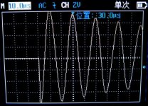
member cwtim01 got a nice result on his pocket oscilloscope in post #375 on the Quasimodo thread. Regrettably I can't read Chinese so I don't know the make and model, see Figure 2 below.
_
member cwtim01 got a nice result on his pocket oscilloscope in post #375 on the Quasimodo thread. Regrettably I can't read Chinese so I don't know the make and model, see Figure 2 below.
_
Attachments
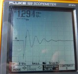
diyAudio member GaryB got a nice result on his Fluke 123 pocket oscilloscope, in post #478 on the Quasimodo thread. Figure 1 below.
member cwtim01 got a nice result on his pocket oscilloscope in post #375 on the Quasimodo thread. Regrettably I can't read Chinese so I don't know the make and model, see Figure 2 below.
_
Mark,
Thanks very much for the heads up! 🙂
Regards,
Dan
So I got one of those $18 oscilloscope kits and tried it out with Quasimodo. See QM thread post #820 for photographs. Summary: no worky.
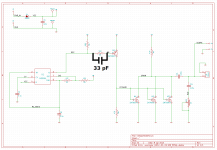
I was noodling around with the Cheapomodo schematic in Post #78, the one with the PNP driver. In LTSPICE simulation it performs ever so slightly better (faster edge rates) when you install a 33 pF capacitor in parallel with the base series resistor, schematic below.
The performance improvement is probably invisible in most situations; I imagine it might only matter when you're testing a transformer with extremely low leakage inductance and, at the same time, operating Cheapomodo from an abnormally low voltage power supply like 3.3V. But still, better is better, even if imperceptably so. 🙂
It's a simple matter to solder this cap straight across the terminals of tbe base resistor. Take a scope photo of a "difficult" transformer before you install the cap, and take another one after the cap. Was the change perceptible? Was it good? (I hope it was).
_
Attachments
May i ask a "newbie" question :
why dont you test the secondaries transformer at it's working tension , and load condition , and /or have you test the snubbing in those conditions ?
in an Amp for example or an Dac , etc ..
tanks for your answer ;-)
.
why dont you test the secondaries transformer at it's working tension , and load condition , and /or have you test the snubbing in those conditions ?
in an Amp for example or an Dac , etc ..
tanks for your answer ;-)
.
fabrice63, I have moved your question over to post #863 in the Quasimodo thread, since you are asking about the idea of bellringers and not about a cheapo way to build one out of junkbox parts ("Cheapomodo").
You can find it at this Link to Quasimodo post #863
If anyone else wants to add their own remarks and comments on the topic, please do so in that thread. Thanks!
You can find it at this Link to Quasimodo post #863
If anyone else wants to add their own remarks and comments on the topic, please do so in that thread. Thanks!
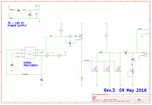
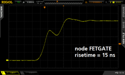
I added the 33pF speedup capacitor to my CheapoModo PCB layout, moved a few things around a bit, and christened it CheapoModo rev3. The slightly faster risetime on node FETGATE is shown below. (post #129 first mentioned this capacitor) The waveform shows the textbook classic "Miller Effect" when the gate of a MOSFET is trying to rise, at the same time its drain is falling quickly.
I've also decided to sell a few kits, and so I've opened a thread in the Vendor's Bazaar for sales purposes: (link). Long-time readers may be surprised to hear that I've started accepting PayPal (gasp!) while offering a substantial discount to purchasers who pay by check instead.
I'm placing the Gerber CAD files in the public domain, they are attached here as a zip archive. Feel free to build these at a PCB fab of your own choice, and feel free to sell them too. Enjoy!
_
Attachments
I tried the cheapo snubber jig too.
I see the ringing on the scope, but also without trafo.
I can reduse the ringing with de Pot, even when de
trafo is not connected. What have i done wrong?
I see the ringing on the scope, but also without trafo.
I can reduse the ringing with de Pot, even when de
trafo is not connected. What have i done wrong?


Thanks dwjames! Nice photos too.
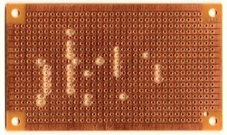
Viewers may wish to study dwj's first photo. You can see that ceramic capacitor C2 (33pF, center top of pic) has had its leads cut much shorter than capacitors C1,3,4 (100,000pF). This is my little way to nudge kit buyers and assemblers, to actually read the markings on the four capacitors and to seek out the different one.
Viewers may wish to study dwj's first photo. You can see that ceramic capacitor C2 (33pF, center top of pic) has had its leads cut much shorter than capacitors C1,3,4 (100,000pF). This is my little way to nudge kit buyers and assemblers, to actually read the markings on the four capacitors and to seek out the different one.
Thanks. I splashed out on a cheapo component tester a while back which makes checking resistors, caps, transistors, diodes etc super quick and easy.

That's with a 3d printed case, they usually look like this

$10 delivered!
That's with a 3d printed case, they usually look like this
$10 delivered!
I have edited post#1 of this thread, and installed a link to the Cheapomodo thread in Vendor's Bazaar.do you have any more kits? If so, I would like to purchase one. Thanks! Andy
Mark, I recently assembled the Cheapomodo you sent and then put it to use on my Soundcraftsmen A2801 power amp. I was amazed how just placing a pair of CRC snubbers across the center tapped secondary outputs using the combo derived with the Cheapomodo caused this big transformer to stop physically buzzing. It has hummed loudly when used since I purchased it back in in 1988. I noted the tranny seemed to be running cooler to the touch as well. I used a 10nF, 100nF, and 100R, as it was a combo I already had the values for on hand which gave me a nice Z of ~1. Next I plan to do the preamp transformer and then my two tube amp power supplies. Question, would this work the same with the output transformers to improve square wave signal ringing? I imagine this would likely cause audible frequency roll off as a result of being in the signal path.
- Home
- Amplifiers
- Power Supplies
- CheapoModo: quick and dirty transformer snubber bellringer jig