Yes.... The Rds on of the three 2n7000s in parallel needs to be low, to allow a high current to flow to ground, to [inject a downward step-function into the transformer secondary] ... To get that fast "kick" [the PNP gatedrive transistor] Q1 needs to pull the gates of the paralleled 2n7000s high. Is that correct? ...
That depends on what you connect to CheapoModo, both now and at some future time, when you're working on a new project with new components and new design constraints.How long do the FET Gates need to be held high?
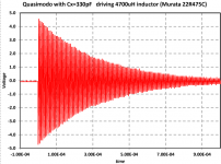
You want your CheapoModo to give the RLC resonant circuit plenty of time to ring like a bell. You also want to give yourself, the human operator of CheapoModo, plenty of time to observe this ringing, and to count off ten or twenty (or fifty!) cycles. Allowing you to estimate the damping factor Zeta by the method of logarithmic decrements (QM appendix B).
One conservative way to proceed might be as follows.
- Estimate the largest value of inductance that you'll ever want to connect to CheapoModo, in the next five years
- Estimate the largest value of (parallel) Cx capacitance that you'll ever want to connect to CheapoModo, in the next five years
- Calculate fmin, the oscillation frequency that results when you connect the inductor of item 1 to the capacitor of item 2
- Calculate twidth, the amount of time encompassed by thirty cycles of oscillation at frequency fmin
- Set the minimum pulse width @ MOSFET gate, to twidth or greater
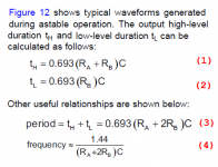
I've also included a snippet from the datasheet of the BJT-process NE555 timer chip used in CheapoModo. These equations will let you calculate the MOSFET-on time and the MOSFET-off time, for the CheapoModo schematic of post #78.
I should point out another way to skin the cat: Redesign CheapoModo so you can vary the MOSFET-on time via DIPswitch settings. I did this myself on the thru-hole PCB "Quasimodo V4" -- but it appears that nobody has ever found this capability to be useful or necessary.
_
Attachments

I have a dubt.
¿Can a snubber modify the reactive power line like a capacitive load?
My DIY ampli have a PF= 0.76.When I add a cap ( for exemple 3 uF) for correct the cosine, it goes to 0.6.I assume that the load is yet capacitive - not usually inductive for a trafo - .
There are only the trafo (inductive) and the snubber (capacitive)
Is the cap of the snubber the culprit?
Cheers
More people will see your question if you create a brand new thread with a descriptive Subject line. Maybe something like
#1: no snubber, no capacitor across primary. Measured power factor = D1
#2: no snubber, 3uF across primary. Measured power factor = D2
#3: CRC snubber, no capacitor across primary. Measured power factor = D3
#4: CRC snubber, 3uF across primary. Measured power factor = D4
Can a CRC snubber across the transformer secondary, modify the power factor measured at the transformer primary?
You could also post some experimental data
#1: no snubber, no capacitor across primary. Measured power factor = D1
#2: no snubber, 3uF across primary. Measured power factor = D2
#3: CRC snubber, no capacitor across primary. Measured power factor = D3
#4: CRC snubber, 3uF across primary. Measured power factor = D4
Thank´s Mark. You are right. Is an other tema.
I try something different and... the modify the power factor is not the snubber.
The cosine goes from 0.97 to 0.76 yet only when the filaments DC voltage are on.The HT application is not important to change this value.
May be to much uF caps of DC filaments power supply?
Who knows.
Cheers
I try something different and... the modify the power factor is not the snubber.
The cosine goes from 0.97 to 0.76 yet only when the filaments DC voltage are on.The HT application is not important to change this value.
May be to much uF caps of DC filaments power supply?
Who knows.
Cheers
Hi !
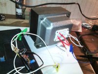
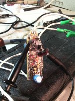
I made a really fast and dirt cheapo modo using original components, it worked the first time, and it seems that a snubber was really necessary ! The xfrm secondaries were winded on a 1,5kw autotransformer, with 4 layer CT of 1mm diameter copper. 2 layers for on 40Vac CT. So 2x40Vac CT, + added 12Vac CT as there were some more room. I put a screen copper layer too. Since it's EI, and not optimised at all, i suspected a snubber would be a good thing...and, as you can see cheapo modo worked really fine...It needs 20ohm (conservative, because found more 15ohm !) on 40Vac CT, and 30ohm for the 12Vac CT !
Does 5 watts resistors would be enough for such low values ???
Attachments

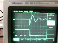
Hi papasteack, that's an excellently damped waveform you've got! Congratulations.
The Quasimodo design note says, on page 7, "a quick SPICE simulation will tell you the power dissipated in the snubber resistor."
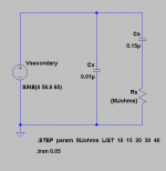
One way to build that SPICE simulation is shown below. It applies the transformer secondary voltage (40V RMS, which is 56.6V peak) to the CRC snubber. Then it monitors the power in the snubber resistor (Rs). The power is its biggest when the AC waveform is at a peak (or trough), and the power is zero when the AC voltage is zero.
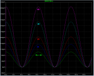
I ran the simulation for several different values of snubber resistor: 10 ohms, 15 ohms, 20, 30, 40 ohms. The results are plotted in different colors. If you have difficulty interpreting the plot, I'm sure some other diyAudio members would be glad to explain it to you.
The Quasimodo design note says, on page 7, "a quick SPICE simulation will tell you the power dissipated in the snubber resistor."
One way to build that SPICE simulation is shown below. It applies the transformer secondary voltage (40V RMS, which is 56.6V peak) to the CRC snubber. Then it monitors the power in the snubber resistor (Rs). The power is its biggest when the AC waveform is at a peak (or trough), and the power is zero when the AC voltage is zero.
I ran the simulation for several different values of snubber resistor: 10 ohms, 15 ohms, 20, 30, 40 ohms. The results are plotted in different colors. If you have difficulty interpreting the plot, I'm sure some other diyAudio members would be glad to explain it to you.
Attachments
Lol...it seems so simple showed like this ^^ I really need more experience !
Thanks a lot Mark for sharing so much time and knowledge here
Thanks a lot Mark for sharing so much time and knowledge here
Tell me Mark, because I have no understanding of SPICE, but don`t mind doing a bit of math, how can I work out the dissipation requirement of the resistor using only pen and paper. Working as I do often on tube amps, i`m more likely to have 400V on my secondaries, so 1200V caps, but what wattage for the resistors is still a mystery to me. I realize there is probably a very complicated answer to this question, but I am also hoping you might have a more, shall we say, practical answer.The Quasimodo design note says, on page 7, "a quick SPICE simulation will tell you the power dissipated in the snubber resistor."
Last edited:
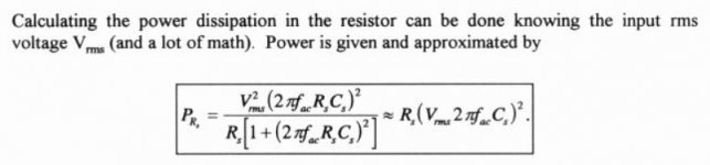
Okay, I just looked back at Hagermans paper and found this. I guess that is the answer, or can you sugest anything else.
Mind you, I just ran that through with Cs 150nF, Rs 100 Ohm, Vrms 400V and 60Hz fac, and get Prs to only be .05. What am I doing wrong? Or is the equasion wrong.
Mind you, I just ran that through with Cs 150nF, Rs 100 Ohm, Vrms 400V and 60Hz fac, and get Prs to only be .05. What am I doing wrong? Or is the equasion wrong.
Attachments
Last edited:
I myself do not feel motivated to re-derive the equations in Hagerman's paper, nor to double-check and validate them. Perhaps you can find an EE who knows how to do this correctly, and then give her/him something nice (cookies? pizza? a drawing?) as compensation & as a way to say thank-you.
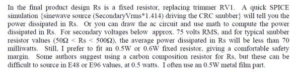
The QM design note includes a few sentences about the power dissipated in the snubbing resistor Rs; they are copied below. I suppose if you were unable to perform the AC circuit analysis + math calculations, AND if you were unable to run SPICE, then in desperation you might try to scale-up those remarks in the Quasimodo design note, to higher voltages.
You might guess/imagine that increasing the secondary voltage by 2X, would increase the snubber power dissipation by 4X (since power is usually proportional to the square of voltage). So if the secondary voltage were 750 volts {a 10X increase over the 75 volts mentioned in the design note}, then power dissipated would be (10 squared) = 100X higher than the 70 milliwatts mentioned in the design note. But don't forget that you are making a desperate guess and not a precise computation.
Attachments
With my example simed (post #86), with the formula (#89) it get around 200uW for 40ohm, and 50uW for 10ohm. On sims, we see max 400uW for 40 ohm, and 100uW for 10ohm.
So formula for my example give so half peak wattage simed. Does it make sense ?
(Supposing i managed to calculate it right... knowing myself, it's not sure ! )
So formula for my example give so half peak wattage simed. Does it make sense ?
(Supposing i managed to calculate it right... knowing myself, it's not sure ! )
There are two components to the power calculation.
You need the AC voltage of the ringing waveform to calculate the power dissipation of the R in series with the capacitor.
If you can measure the height of the ringing waveform, when the wrong resistor is used, then calculate the current and determine the dissipation.
But we don't want the ringing waveform. We want the snubbed waveform.
The dissipated power lasts half a cycle and the voltage is tiny, when there is no resonant peak.
Why try to calculate whether it's 10uW or 100uW?
The second component:
The Mains AC voltage does pass through the R+C snubber, but the current is also miniscule.
This one is easy to calculate.
Assume the Xc of the capacitor is the substantial impedance provided to the Mains AC waveform.
Calculate the 50/60Hz current passing the C and then for the resistor use P=I²R to see that the resistor dissipates <1mW @ 50/60Hz.
Last edited:
I don't understand anything 😛 ; it seems that this little hobby will make me opening books soon or later 
If you know what to do,maybe.This one is easy to calculate.
Xc=1/(2pi f C)...........so for 150n @ 60Hz = ca.18k , for 150n @ 50Hz = ca.22kAssume the Xc of the capacitor is the substantial impedance provided to the Mains AC waveform.
I=V/R Using my 400V example from before 400/18000 = .02222 ampreCalculate the 50/60Hz current passing the C
P=I²R .0222² X 100 = .049 watts - the same I got with the PR= R(V2pifC)²and then for the resistor use P=I²R to see that the resistor dissipates <1mW @ 50/60Hz.
or have I missunderstood something maybe.
That's the power due to passing the mains voltage.
Then the difficult bit due to the HF ringing voltage.
BTW,
I would not use 150nF on a 400Vac supply.
Whose capacitor are you intending to use?
What limits do they place on voltage and current etc?
Then the difficult bit due to the HF ringing voltage.
BTW,
I would not use 150nF on a 400Vac supply.
Whose capacitor are you intending to use?
What limits do they place on voltage and current etc?
Would this not be, not ignorable, but a negligable value by comparison at higher voltages?That's the power due to passing the mains voltage.
Then the difficult bit due to the HF ringing voltage.
It was just an example value, but would you care to elaborate.BTW,
I would not use 150nF on a 400Vac supply.
-------------------------------
Pity the sorrows of the poor blind,
For they can but little comfort find;
As they walk along the street,
They know not where to put their feet.
William McGonagall
Wima FKP 1 WIMA should be up to it.Whose capacitor are you intending to use?
What limits do they place on voltage and current etc?
Let me guess; A 400v secondary will probably have a queit high inductance, so using a 150n Cap will mean I will will have a low resonant frequency, causing possibly a larger resonance than I would get with a smaller cap, that will need a higher value resistor to damp it, meaning higher dissipation requirements. - Am I on the right track?I would not use 150nF on a 400Vac supply.
- Home
- Amplifiers
- Power Supplies
- CheapoModo: quick and dirty transformer snubber bellringer jig