I've never tried that.
Don't forget that Cheapomodo testing requires you to connect a dead short across all other secondary windings and all primary windings. See the Quasimodo design note, Figure 13. Perhaps your tests accidentally had one or more windings that weren't shorted.
Don't forget that Cheapomodo testing requires you to connect a dead short across all other secondary windings and all primary windings. See the Quasimodo design note, Figure 13. Perhaps your tests accidentally had one or more windings that weren't shorted.
does this requirement for the primary to be shorted mean that one cannot "test" an installed transformer?I've never tried that.
Don't forget that Cheapomodo testing requires you to connect a dead short across all other secondary windings and all primary windings. See the Quasimodo design note, Figure 13. Perhaps your tests accidentally had one or more windings that weren't shorted.
The primary will either be open circuit, or connected the the low impedance of the mains and thus live.
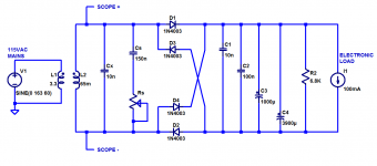
Is it possible to verify that the actual snubber connected across the secondary is working by using the CheapoModo? The first attachment is the trace I get when inserting the actual parts I ordered in the CheapoModo and connecting to one secondary. The second attachment is the snubber installed in the transformer secondary. The third attachment is the trace I get with Cx, Cs, and Rs removed from CheapoModo, but having it connected to the transformer with snubber installed.
View attachment 602493 View attachment 602497View attachment 602494
interesting question - in addition to the snubber network what are the blue and green secondary wires connected to ? A diode bridge + cap bank + load ?
PS. Why does one leg of the snubber network look like its left unsoldered from the tap on the green wire ?
does this requirement for the primary to be shorted mean that one cannot "test" an installed transformer?
The primary will either be open circuit, or connected the the low impedance of the mains and thus live.
That's a good point @AndrewT. I had wondered about that, too. Could it be that the low impedance of the the mains supply acts similar enough to shorting the primary? I also wondered if shorting the primary with a low value resistor in the loop may be a closer approximation. No doubt the HF behaviour would differ.
One could temporarily short the primary and then test the installed transformer.
This could be done at the mains plug across the exposed pins.
The loads on the other secondaries would be effective shorts.
I hope Mark comes back with a proper method.
This could be done at the mains plug across the exposed pins.
The loads on the other secondaries would be effective shorts.
I hope Mark comes back with a proper method.
interesting question - in addition to the snubber network what are the blue and green secondary wires connected to ? A diode bridge + cap bank + load ?
PS. Why does one leg of the snubber network look like its left unsoldered from the tap on the green wire ?
The secondary wires are not connected to anything other than the Cheapomodo.
It was difficult to solder the components to the 10 gauge wire coming from the transformer. A cold solder joint broke, I was hoping no one would notice. You guys don't miss a thing. That was repaired and has nothing to do with the trace in attachment 3.
Cheapomodo and its big brother Quasimodo were conceived as bench-only test jigs. They are designed to be connected to a transformer and nothing else. In particular, no power switch, no rectifiers, no fuse, no IEC RFI inlet filter, and no surge protector. When I cooked up the bellringer idea, I imagined that if I wanted to optimize a snubber for a piece of existing equipment, I would disconnect all of its transformer's wires and physically remove the trafo from the chassis. I'd place it on my bench, all by itself, for bellringer testing.
I myself have never tried to attach a bellringer to the internal guts of a piece of equipment, in which the transformer is connected to a fully operational power supply. It might work, but I doubt it. The way to find out is to locate someone who used a bellringer to optimize a (transformer + snubber) before installing the transformer and snubber into a piece of audio gear. Thanks to properly executed bellringer tests on an isolated transformer on the bench, you know The Right Answer beforehand. Perform your various rude and naughty experiments, connecting up a Cheapomodo and scope to the final gear, and discover whether any of them give The Right Answer. It might work, but I doubt it. If it does, you now have a measurement protocol. Congratulations.
Readers might wish to consider this to be a design challenge. Design a brand new test-jig that can be connected to a complete and finished piece of audio equipment, and dial up an optimized snubber for that piece of gear. I suppose one critical requirement would be: No Unsoldering, No Disconnecting allowed. Probably it is okay to ask the user to unplug the AC mains plug and short its pins with crocodile clips. But if you can manage to do the tests without shorting the mains plug, so much the better.
By the way, over in another thread I showed 3 different transformers, comparing (a) ringing frequency on Cheapomodo; versus (b) ringing frequency in a real power supply using TERRIBLE AWFUL diodes. The ringing frequencies were very similar, which just means that the transformer's leakage inductance didn't change much. Not a big surprise.
Here is the link.
Mark, was the test circuit on the secondary side, and the core, grounded to mains side protective earth for those tests, or were the core and secondary side floating?
I noticed in your latter post that you sort of confirmed the snubber was effectively removed in both those test set ups, even though it is shown in the schems (in order to better observe the resonant waveform).
And can you confirm that all transformer windings were in circuit for both tests, ie. for the R-core, were the primaries in parallel and the secondaries in parallel ?
Last edited:
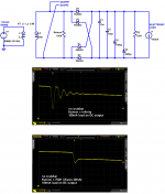
Cx=10nF was fitted. Cs=150nF was fitted. Rs was unsocketed (infinity ohms) to make it easier to measure the ringing frequency and confirm / disconfirm the results from diyAudio member DNi. It was the exact schematic shown below, with actual live mains AC applied (USA 115V) at the left and actual live electronic load connected at the right. Rs = infinity. To no-one's great surprise, the ringing frequency was the same whether (Lleakage + Cx) was resonating in the bellringer jig, or in the linear power supply shown here.
Spend a dozen seconds calculating Lleakage given Cx and f_ringing; it is a startling number of femtohenries.
_
Spend a dozen seconds calculating Lleakage given Cx and f_ringing; it is a startling number of femtohenries.
_
Attachments
Ta, thanks for confirming the snubber was effectively removed for the tests. Can you recall if anything was grounded, as per practical equipment setup?
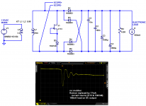
A single Cx straight across the secondary is a snubber, at least in some people's opinion. Neurochrome's website says so, for example. Image below.
And if you experiment with your own Cheapomodo you can verify that Cx all by itself, does in fact change the secondary's ringing waveform amplitude, frequency, and Q (damping). Does that make Cx a "snubber" all by itself? Some people think so.
_
And if you experiment with your own Cheapomodo you can verify that Cx all by itself, does in fact change the secondary's ringing waveform amplitude, frequency, and Q (damping). Does that make Cx a "snubber" all by itself? Some people think so.
_
Attachments
Last edited:
The Cx has to be in the 'power supply' test as that part is intrinsically required in the comparison bellringer test rig, so is needed for apples-apples.
The clarification was about the tuned RC part of the snubber. Same as the other clarification enquiries, its good to be specific about test comparisons when information is available. That may assist others if they do similar tests, or tests where other parasitics become significant.
I also appreciated viewing the tests you did in post #91102 and 99107 (and earlier) of that very very long thread:
http://www.diyaudio.com/forums/lounge/146693-john-curls-blowtorch-preamplifier-part-ii-9111.html
I have built this jig in a dead bug style in twenty minutes. It costs me one Euro, all parts in a local shop.
In my flatpack split primary and secondary transformer , leakage ind. is very high , 16mH and optimal R value is about 1K1. At the same time I measured with my USB scope ringing directly in PS , and observed that single resistor of 3K3 on each secondary , as forum member Simon suggested, reduced ringing almost as full CRC snubber. For low current eq. CRC snubber is not necessary.
I have to learn how to download images from my new USB scope.
BTW, there is no any improvement in sound in my snubbered phono stage.
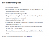
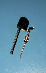
diyAudio member simon7000 and I fooled around with R-only snubbers last month. I took the scope photos shown below.
We tested (and disproved!) the hypothesis that the resistor prevents the transformer from suddenly "un-loading" -- its secondary current suddenly snaps to zero -- when the diode switches off, and it is this "un-loading" which allows ringing to occur. According to this false hypothesis, by connecting a resistor straight across the secondary, a healthy amount of current continues to flow in the secondary when the diode switches off, and ringing is prevented.
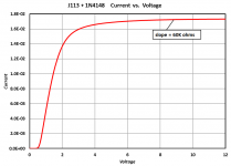
This was disproved by replacing the resistor with a constant current source whose Norton output resistance was 60 Kohms. Same current flows but -- Shazam! -- ringing persists.
The explanation is straightforward: the resistor is simply the "R" part of the RLC resonant circuit in the secondary, and it damps the oscillatory ringing. Just like they teach in Linear Systems Theory at EE school: R = (1/(2*Zeta))*sqrt(L/C).
Connecting a single R across the secondary becomes more and more impractical when (a) transformers with higher secondary voltages are used; (b) transformers with lower leakage inductances are used. The power dissipated in the resistor becomes unacceptably large in both situations, which is why the more universal snubbing solution connects a capacitor in series with the damping resistor.
edit- by the way, the Gerber CAD files for the little test PCB shown here, are attached to this DIYA post. Anybody who wants to, can download these Gerbers and send them off to China to have boards fabbed, $12 for 10 boards. Feel free to do your own snubbing experiments! It's fun! It's educational! It's real world science.
_
We tested (and disproved!) the hypothesis that the resistor prevents the transformer from suddenly "un-loading" -- its secondary current suddenly snaps to zero -- when the diode switches off, and it is this "un-loading" which allows ringing to occur. According to this false hypothesis, by connecting a resistor straight across the secondary, a healthy amount of current continues to flow in the secondary when the diode switches off, and ringing is prevented.
This was disproved by replacing the resistor with a constant current source whose Norton output resistance was 60 Kohms. Same current flows but -- Shazam! -- ringing persists.
The explanation is straightforward: the resistor is simply the "R" part of the RLC resonant circuit in the secondary, and it damps the oscillatory ringing. Just like they teach in Linear Systems Theory at EE school: R = (1/(2*Zeta))*sqrt(L/C).
Connecting a single R across the secondary becomes more and more impractical when (a) transformers with higher secondary voltages are used; (b) transformers with lower leakage inductances are used. The power dissipated in the resistor becomes unacceptably large in both situations, which is why the more universal snubbing solution connects a capacitor in series with the damping resistor.
edit- by the way, the Gerber CAD files for the little test PCB shown here, are attached to this DIYA post. Anybody who wants to, can download these Gerbers and send them off to China to have boards fabbed, $12 for 10 boards. Feel free to do your own snubbing experiments! It's fun! It's educational! It's real world science.
_
Attachments
Last edited:
In other words, resistor-only snubber is effective in reducing ringing if power dissipation is within limits of resistor ratings. In my case , I tried 0.6W resistor across 36V sec. voltage and dissipation is 0.39W.
If you try it with a 300VA toroidal transformer whose leakage inductance is < 20 microhenries, you'll need at least a 5 watt resistor; most likely 10W. Be careful not to use wirewound resistors for snubbing; they are inductive.
I measured an Antek AS-2222 a couple years ago; its secondary leakage inductance was less than 10uH.
I measured an Antek AS-2222 a couple years ago; its secondary leakage inductance was less than 10uH.
36Vac and 3k3 as a snubbing load dissipates 0.39W.In other words, resistor-only snubber is effective in reducing ringing if power dissipation is within limits of resistor ratings. In my case , I tried 0.6W resistor across 36V sec. voltage and dissipation is 0.39W.
That's a very high value for a snubbing resistor.
Most are well below 1k0 and some are getting down to around 30r.
My transformer is flatpack ,PCB type with high inductance and very low capacitance between primary and secondary. 3k3 resistor was value that gave me the lowest ringing on oscilloscope. With CRC snubber I got 1K1 as the best value.Anyway, I am sad for not getting any improvement in sound quality of my LP-s which is already superb.36Vac and 3k3 as a snubbing load dissipates 0.39W.
That's a very high value for a snubbing resistor.
Most are well below 1k0 and some are getting down to around 30r.
I have tested both CRC and single resistor.My phono stage regulators are Jung Super reg . with high PSRR up to high frequencies.Perhaps there is a filtering of noise produced by transformer and diode bridge.Here is a post from someone who heard a big difference when he connected various snubbers to his vacuum tube audio equipment: link
However I don't think he tried to snub his gear using 1-resistor, 0-capacitor circuitry.
- Home
- Amplifiers
- Power Supplies
- CheapoModo: quick and dirty transformer snubber bellringer jig