Turned around and I get pretty much the same as my first photo. About as good as I can get it. Turning either way just seems to produce less damping.
Last edited:
It sounds like you might have accidentally plugged Cx where Cs is supposed to go, and plugged Cs where Cx is supposed to go. It's worth checking.
I think you may want to back up and find out whether the problem is with your CheapoModo board, or with the Cs, Cx, Rtrimmer, or with the transformer.
One experiment that always boosts people's confidence, is to temporarily disconnect the transformer secondary, and instead connect a fixed inductor of known value, something between 5 uH and 220 uH, in its place. See whether Quasomodo can damp this RLC circuit to give Zeta=1.0. If it can then you feel more confident in your board and in your lab technique. It it can't then you are certain the problem is with the tester and not with the transformer.
You might need to try a 200 ohm trimmer or even a 50 ohm trimmer, just so you can slowly and methodically explore the very low-ohms end of the potentiometer's travel.
How do you have the transformer connected?
This is from the data sheet:
Connections:
Input: Series – Pin 1 to Pin 6, Jumper Pin 4 to Pin 3
Parallel – Pin 1 to Pin 6, Jumper Pin 1 to Pin 4 and Pin 3 to Pin 6
Output: Series – Pin 7 to Pin 12, Jumper Pin 9 to Pin 10
Parallel – Pin 7 to Pin 12, Jumper Pin 7 to Pin 10 and Pin 9 to Pin 12
This is from the data sheet:
Connections:
Input: Series – Pin 1 to Pin 6, Jumper Pin 4 to Pin 3
Parallel – Pin 1 to Pin 6, Jumper Pin 1 to Pin 4 and Pin 3 to Pin 6
Output: Series – Pin 7 to Pin 12, Jumper Pin 9 to Pin 10
Parallel – Pin 7 to Pin 12, Jumper Pin 7 to Pin 10 and Pin 9 to Pin 12
I checked Cx and Cs and both are correct. I don't have a choke in my parts collection...seriously, I don't. Haha.
I did swap out Cs for a 2.2uF box cap. I think I now get the textbook example, but I'll wait for the judge's decision.

Going out for a bit but will check the pin connections on the xformer later and post what I have. Next time I pass Fry's, I'll pick up a choke.
I did swap out Cs for a 2.2uF box cap. I think I now get the textbook example, but I'll wait for the judge's decision.
Going out for a bit but will check the pin connections on the xformer later and post what I have. Next time I pass Fry's, I'll pick up a choke.
From Page 11, Fig. 13 of the Quasimodo, I used the 3rd diagram for the 2 independent secondaries and wired it thus:
Primary:
Pin 1 to Pin 6
Pin 3 to Pin 6
Pin 1 to Pin 4
(this is the same as you have as parallel)
Secondary:
Pin 7 to Pin 9 (this shorts one of the secondaries, per fig. 13 in the Quasimodo guide)
Measurement:
Pin 10 and Pin 12 (I add a full wave rectifier to each independent secondary)
Primary:
Pin 1 to Pin 6
Pin 3 to Pin 6
Pin 1 to Pin 4
(this is the same as you have as parallel)
Secondary:
Pin 7 to Pin 9 (this shorts one of the secondaries, per fig. 13 in the Quasimodo guide)
Measurement:
Pin 10 and Pin 12 (I add a full wave rectifier to each independent secondary)
Last edited:
Since I didn't have a choke handy, I do have various transformers in my parts box. So I grabbed a small Antek toroidal, hooked it up, and made sure to put back the default Cs cap.
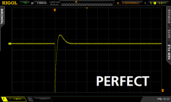
This transformer was easier to dial in, as seen here. No problems with this one compared to the dual bobbin I had earlier.

This transformer was easier to dial in, as seen here. No problems with this one compared to the dual bobbin I had earlier.
Fun about to begin!
P.S. Thanks Mark for the kit.
An externally hosted image should be here but it was not working when we last tested it.
P.S. Thanks Mark for the kit.
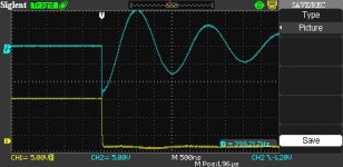
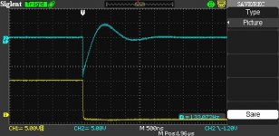
Alright, I got the board working, I think. Plugged it in to my AN-10445 and got this output on the oscilloscope. The Rs goes from infinity down to 41 Ohm and down to 28.5 Ohm. If I reduce resistance the line flattens even more... What is the optimal value for Rs? Why can't I just short it out?
Attachments

Can you dial in the Rs value even lower?
Looking at your plots, it seems to me that 41ohms is still ringing a bit.
28r5 seems close to optimum. Maybe optimum is somewhere between 20ohms and 30ohms.
Try 10ohms and 5ohms and compare to your existing plots.
C+R = snubber when the resistor absorbs energy and thus damps the ringing.
If R is made infinite, no current flows and no energy is absorbed and no damping ocurrs.
If R is made zero then current flows through the capacitor but the resistor absorbs no energy and thus no damping of the ringing.
Last edited:
Can you dial in the Rs value even lower?
Looking at your plots, it seems to me that 41ohms is still ringing a bit.
28r5 seems close to optimum. Maybe optimum is somewhere between 20ohms and 30ohms.
Try 10ohms and 5ohms and compare to your existing plots.
C+R = snubber when the resistor absorbs energy and thus damps the ringing.
If R is made infinite, no current flows and no energy is absorbed and no damping ocurrs.
If R is made zero then current flows through the capacitor but the resistor absorbs no energy and thus no dampinging of the ringing.
+1
Thanks for the detailed explanation, Andrew, I will try smaller values later today.
By the way, what wattage should I go for the resistor in PSU? My calculations show that 0.15mF capacitor impedance will be 2.6K at the transformer's resonance frequency 400Hz. The secondary AC voltage is 45V thus the resistor will dissipate around 0.5 Watt at 30 Ohm and I should go with 1 Watt rated part to be safe. Do these numbers look OK?
By the way, what wattage should I go for the resistor in PSU? My calculations show that 0.15mF capacitor impedance will be 2.6K at the transformer's resonance frequency 400Hz. The secondary AC voltage is 45V thus the resistor will dissipate around 0.5 Watt at 30 Ohm and I should go with 1 Watt rated part to be safe. Do these numbers look OK?
Last edited:
the combined impedance of the capacitor (at one frequency) and the resistor is given by
Impedance = sqrt(cap impedance^2 + resistor impedance^2)
If for 400Hz you have C= 2600ohms and R= 28.5ohms, then the combined impedance is 2600.156ohms.
The current through the snubber will be Vac @ 400Hz/Impedance = 0.1Vac / 2600.156ohms = 0.038mAac
The resistor will have to dissipate: Pdiss = 0.000038^2Aac * 28.5 ohms = 42nanowatts ! when the 400Hz element of the ringing is 0.1Vac continuously.
If your system had 1Vac @ 400Hz continuously, then the Pdiss goes up to 4.1microwatts.
A 1/10th watt smd resistor will stay cold.
That is also why the 400milliwatt VR does not burn out.
A 200ohm 500mW VR has a maximum current rating of 50mA
A 10kohm 400mW VR has a maximum current rating of 6.3mA, (this is 165times the 400Hz 0.1Vac ringing current).
Last edited:
Where does the 0.1Vac come from? I used full secondaries 45Vac in my calculations (as the worst case of what resonant potential can be).
I took a guess at the ringing voltage.
The 50/60Hz voltage may be 45Vac, but that is not the voltage of the 400Hz part of that waveform.
But you can use the same method to calculate the current through the snubber for the 50Hz or 60Hz mains frequency @ 45Vac and add that 50/60Hz Pdiss onto the 400Hz Pdiss. Then estimate the 2nd harmonic voltage and the third harmonic voltage, etc and add them all up.
Why are you using 0.15milliFarad capacitor?
Should that be 0.15microFarad = 150nanoFarad = 150nF?
or should it be 1uF to give 2652.6ohms @ 60Hz?
The 50/60Hz voltage may be 45Vac, but that is not the voltage of the 400Hz part of that waveform.
But you can use the same method to calculate the current through the snubber for the 50Hz or 60Hz mains frequency @ 45Vac and add that 50/60Hz Pdiss onto the 400Hz Pdiss. Then estimate the 2nd harmonic voltage and the third harmonic voltage, etc and add them all up.
Sorry Moderators: that came from post211, if you really need attribution.My calculations show that 0.15mF capacitor impedance will be 2.6K
Why are you using 0.15milliFarad capacitor?
Should that be 0.15microFarad = 150nanoFarad = 150nF?
or should it be 1uF to give 2652.6ohms @ 60Hz?
Last edited:
Oh, I see. I will try some of these calculations at home.
Did you take a guess at 0.1Vac based on your hunch, or did you somehow see it in the scope charts I posted? Sorry, I am just trying to understand how this works.
Did you take a guess at 0.1Vac based on your hunch, or did you somehow see it in the scope charts I posted? Sorry, I am just trying to understand how this works.
Sorry about the confusion, 0.15mF is me not finding the character for 'micro' on my keyboard. The impedance was calculated for the correct value of 0.15 microfarad @ 400 Hz, not 0.15 millifarad
Last edited:
capacitor impedance = 1/{2 Pi Freq Capacitance}
I used to use ALT+0181 to place micro on the screen.
But some automatic update now uses the alt+ key as a hotkey to close the browser and return to my previous job.
I used to use ALT+0181 to place micro on the screen.
But some automatic update now uses the alt+ key as a hotkey to close the browser and return to my previous job.
Last edited:
What is the optimal value for Rs?
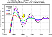
The optimum value of Rs is the value which juuuuust barely manages to flatten the 2nd hump in the waveform. The 2nd hump is indicated by the yellow arrow in Figures 10 and 11 of the Quasimodo design note (below). The setting of Rs which gives the red waveform, is optimum for this transformer + Cx + Cs.
_
Attachments
Last edited:
Alright, the way I understand this explanation is that I will keep reducing Rs until I don't see the second hump, but not beyond that point, right?
In that case, going to the scope pictures I posted I'm my earlier post, 28.5 Ohm is perfect. I flattened the second hump (which was still visible on the 41 Ohm picture) but not more.
If I keep reducing Rs the snubber will not serve it's purpose (even though from the scope it looks like I keep flattening resonance output). Why so? I was fully expecting the resonance to start picking up as I keep lowering Rs down to 0, however I don't see this happening
- Home
- Amplifiers
- Power Supplies
- CheapoModo: quick and dirty transformer snubber bellringer jig