Just noticed the lower supply voltage to the front end, and you already commented. Thanks I see it now, makes sense.
I'm sure that your amps work very well, I'd just prefer to use parts that are
known not to have the issue. As far as I know all current IRFP9240s from
IR have the issue.
Thanks, nice design by the way, curious to hear what you find.
Is your clever drive to the VAS used in any OP amps or is it completely original?
Any suggestions for output protection? Fuses good enough with the robust
output devices?
I use Vishay MOSFETS in this my design with good result.
http://www.diyaudio.com/forums/solid-state/243481-200w-mosfet-cfa-amp-92.html#post4580555
Last edited:
P.S. Ah, I see - Albert is using BD139/140. I recommend 2SC3503/1381.
The BDs are used in my simulation with TINA, it does not have the 2SC3503/1381 models. Later on I switched to Micro-Cap but it only had the 2SA1381 pnp complement. In my build I will be using 2SC3600/SA1406 pair. I have started populating my boards,... I just hope I won't ran into trouble with my acquired IRF devices, they are of different manufacturer one with an S looking brand and the other was a Fairchild made.
@Terry,
..perhaps a sofstart and a ground loop breaker could eliminate the turn on thump...I once cured an amp with a nasty turn on thump by applying this. Was there a hiissing sound while it is on? (when no music is played).
I made the input lay-out as farthest from any current sources, so that it won't catch any possible sources of contamination and produce the cleanest input signal possible 😉
100x100mm
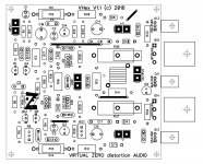
My version of the layout 😉
Squeezed it to 100x100mm square board.
Etching-friendly - single-sided, 4 jumper wires.
My version of the layout 😉
Squeezed it to 100x100mm square board.
Etching-friendly - single-sided, 4 jumper wires.
Attachments
Was there a hiissing sound while it is on? (when no music is played).
It's virtually silent with no signal. I tested this front-end with the other OPS.
Low noise LTP (2N5089) and 29db overall gain = no hiss 😎
The amp is dead quiet. Turn on sounds like a puff of air. Like fffffaaa. Offset is a couple volts at startup and settles quickly. It's not drastic but worth noting. There is no sound at power down.


My version of the layout 😉
Squeezed it to 100x100mm square board.
Etching-friendly - single-sided, 4 jumper wires.
Oops! Forgot the base stoppers for the drivers. It happens sometimes as a result of manual re-drawing of the schematic in DipTrace ((
I also noticed you have not included the zobel network, are they supposed to be installed offboard?
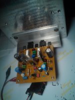
.....one channel populated, a few work on drilling holes and ready for the test. 😉 Not as good lookin as Terrys.
It is funny though I am working on a hi-speed design at a slow rate of work...

.....one channel populated, a few work on drilling holes and ready for the test. 😉 Not as good lookin as Terrys.
It is funny though I am working on a hi-speed design at a slow rate of work...
Attachments
I also noticed you have not included the zobel network, are they supposed to be installed offboard?
.....one channel populated, a few work on drilling holes and ready for the test. 😉 Not as good lookin as Terrys.
It is funny though I am working on a hi-speed design at a slow rate of work...
Zobel - this amp has got stability margins really high, so I just omit it. Although, the inductor is still important for the case of the highly capacitive load.
Looking good, cool local heatsinks. Just ... that TO-264 package looks odd - that's not IRFP one, right? 🙄
There's a Russian proverb, saying that Russians harness the horse slowly, but ride fast. That's exactly the case here then 😛
Looking good, cool local heatsinks. Just ... that TO-264 package looks odd - that's not IRFP one, right? 🙄
It is an IRFP240A with the "f" logo in its case. Possibly a Fairchild device or a "fake" one. 😕
The TO-126 heatsink are actually for Class D amp use. I installed them just for a test, I like the angular DIY made (like that of Terrys build).
It is good to know that the design does not need the zobel, this makes the pcb lay-out to be more compact. When I think of "speed" in a design I believe pcb trace distance width and copper zone plays an important role at nanosecond travel rate of voltage/current. 😉
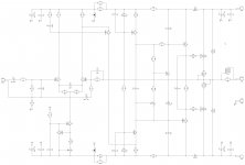
I have a question I was not ablte to get the VBE to work as drawn. Thinking the linking was wrong, I changed it so the trimmer was inline with the 1k8 resistor and changed the trimmer to a 500R. Now I can set the bias but obviously this is not wired correctly. Here is what I have. With the trimmer attached between the 1k8 resistor it is set to 350R. This give a bias of 80mA. What would need to be changed in order for the trimmer to be in the correct location? I'm attaching a schematic with what I have now.
Attachments

I have a question I was not ablte to get the VBE to work as drawn. Thinking the linking was wrong, I changed it so the trimmer was inline with the 1k8 resistor and changed the trimmer to a 500R. Now I can set the bias but obviously this is not wired correctly. Here is what I have. With the trimmer attached between the 1k8 resistor it is set to 350R. This give a bias of 80mA. What would need to be changed in order for the trimmer to be in the correct location? I'm attaching a schematic with what I have now.
Hi Terry,
As soon as you wire it correctly, the bias is going to decrease. Try to increase it with the trimmer. If it does not reach the desired value, slightly decrease R10 and try again. The lower R10+R11 - the higher the bias.
Cheers,
Valery
Well then I have something else wrong because the bias is too high with it connected correctly. I will do some more investigating. It is working perfectly right now.
Well then I have something else wrong because the bias is too high with it connected correctly. I will do some more investigating. It is working perfectly right now.
Then you can try to increase R10 - the bias will decrease. If everything else is ok.
Actually, in my simulation, I've got R10 = 560R as an optimal value.
You can start with, say, 680R and see if the bias is going to be too low and see what direction you go next. Again - higher R value -> lower bias and vice versa.
You can start with, say, 680R and see if the bias is going to be too low and see what direction you go next. Again - higher R value -> lower bias and vice versa.
Terribly sorry, I do have it hooked up properly. I did have to change the way that Albert had it wired in his sprint file. After inspecting it more closely the 510 resistor is in series with the trimmer. I just remeasured and the trimmer is set to 230R on one channel and 220R on the other. Is there any advantage to using higher value for R110 and low value for the trimmer?
Terry, Valery,
The Vbe multiplier on any amp is incredibly tetchy and this one is special because of the red LED, which modifies the tempco so it doesn't over compensate on the warming outputs.
I'm very impressed with it, Valery, in my amps I reduce the tempco by using a simple Vbe multiplier in series with a zero tempco 4.7V zener. On hexfets the gate to gate voltage is around 8.25V for AB operation and only 3.5V across the BD139 Vbe multiplier is needed to effect precise quiescent current. The idea of a 1.6V led, which is almost zero tempco, reduces the tempco to less than 30% (2.25/0.65) compared to a full Vbe multiplier across the gate to gate 8.25V.
Valery, did you try this amp without the drivers on the gates? Here's a question: Since we are dealing with music up to 20KHz (hopefully!) we don't need to move charge into the gates as we turn on the hexfets. But how about removing the charge when we turn them off? Is this more important?
It is the fine detail and acute understanding of the AB audio amplifier the makes Valery innovative and insightful........
Hugh
Last edited:
Terry, Valery,
The Vbe multiplier on any amp is incredibly tetchy and this one is special because of the red LED, which modifies the tempco so it doesn't over compensate on the warming outputs.
I'm very impressed with it, Valery, in my amps I reduce the tempco by using a simple Vbe multiplier in series with a zero tempco 4.7V zener. On hexfets the gate to gate voltage is around 8.25V for AB operation and only 3.5V across the BD139 Vbe multiplier is needed to effect precise quiescent current. The idea of a 1.6V led, which is almost zero tempco, reduces the tempco to less than 30% (2.25/0.65) compared to a full Vbe multiplier across the gate to gate 8.25V.
Valery, did you try this amp without the drivers on the gates? Here's a question: Since we are dealing with music up to 20KHz (hopefully!) we don't need to move charge into the gates as we turn on the hexfets. But how about removing the charge when we turn them off? Is this more important?
It is the fine detail and acute understanding of the AB audio amplifier the makes Valery innovative and insightful........
Hugh
Hi Hugh,
Absolutely - Vbe multiplier is an important and sometimes "tricky" thing, under-valued by some designers 😉
An idea of the red LED was developed some time ago when I decided to use an existing BJT-based EF3 output stage as a basis for converting it into a HexFET-based one (using the printed boards I already had).
I have removed the pre-drivers and realised I still need to reduce thermal sensitivity of the spreader. During discussion at that time, Jason (jkuetemann) proposed using the LED for correcting the tempco curve. Live tests showed very good results.
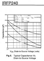
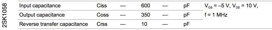
With regards to "no drivers" approach - HexFETs have got rather high and non-linear input capacitance (depends on Vgs), noticeably influencing VAS performance. Live measurements just confirm the theory - spectrums contain higher number of odd harmonics with higher levels. That's why I always add the follower - as soon as you drive the HexFETs with low impedance drivers, capacitance issue does not hurt any more.
Lateral FETs - completely different story. Those ones are designed for audio applications, capacitances are not that high and rather linear. Unfortunately I've got no graph for them, but again - live measurements show good results with them, being driven directly from the VAS, just a bit higher VAS quiescent current is recommended (8-10mA is good). All this beauty is also not given for free - lateral FETs are prone to local oscillation at very high frequencies (can exceed 100MHz), especially if more than one output pair is used. Well, not a show stopper - just needs to be addressed properly 😎
Cheers,
Valery
P.S. And you're right - removing the charge is more important. As usual, they close slower than they open. Well, 0.1-1uF cap between the emitters of the drivers works well enough.
Attachments
Last edited:
Terry,
How did you managed to make your amp working....mine, at power-on bias LED lit up momentarily then goes out. The other CCS LEDs are totally off. I can only get around 10vdc at drain pins and at the collector of drivers. I have also measured a small voltage at zener of +rail, but 0volt on the - rail. I suspect that fake looking IRFP240 device is faulty but the bias circuit seemed to be working properly because adjusting the trimmer, both fets gets much warmer...
I have corrected the missing ground ref trace in my board and the bias LED orientation. Also the mains 100w bulb tester is lit dimly, I am tempted to remove the thing because I was suspecting the fets does not get enough current to work properly..😕
- Home
- Amplifiers
- Solid State
- IRFP240/9240 Amplifier (simulated on TINA)