Terry, if you'd like to move the range of quiescent current to the lower values, you can increase 510R. 620R will be just about right, I think.
The higher overall resistors' value below the spreader's base - the lower the outputs' quiescent current is.
Hi Valery,
Thanks for that. I already installed 500R trimmers and they are about perfect. They end up pretty much centered at about 90mA.
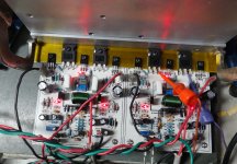
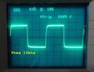
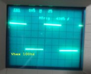
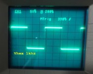
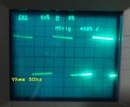
I have it singing and listened to it for about an hour. Very nice as expected. Here's some pics.
EDIT: I forgot to mention that the offset trimmer is maxed out on both channels. It does achieve 2mV but you might want a little more room.
Attachments
Last edited:
Hi Valery,
Thanks for that. I already installed 500R trimmers and they are about perfect. They end up pretty much centered at about 90mA.
I have it singing and listened to it for about an hour. Very nice as expected. Here's some pics.
EDIT: I forgot to mention that the offset trimmer is maxed out on both channels. It does achieve 2mV but you might want a little more room.
Looks nice and clean!
The offset - you can slightly increase 240R (sitting in series with offset trimmer) - this will move the threshold in the right direction.
A new member in amplifiers family.
To help other guys, please post the final schematic and pcb, as built, in one new post.😉
To help other guys, please post the final schematic and pcb, as built, in one new post.😉
I think Albert is planning to use different values than I did. Maybe we should wait until he has his singing.
Excellent work Terry,
I'm kinda busy here rigt now helping out with my sister's school reports. School days are over, it is summertime! I am very eager to work with my amp too, I knew the PCB will work with nice results.
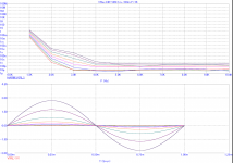
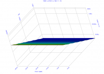
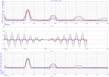
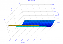
Meanwhile I just learned how to extract these datas in Mikro Cap, using the original schematic (Valery's). 😉
Intermodulation Distortion Analysis and THD in 3D.
I'm kinda busy here rigt now helping out with my sister's school reports. School days are over, it is summertime! I am very eager to work with my amp too, I knew the PCB will work with nice results.
Meanwhile I just learned how to extract these datas in Mikro Cap, using the original schematic (Valery's). 😉
Intermodulation Distortion Analysis and THD in 3D.
Attachments
A new member in amplifiers family.
To help other guys, please post the final schematic and pcb, as built, in one new post.😉
Terry can share his pdf, it is officially working. I have no plans in revising the lay-out, it is by far the most compact 😉
As for the final schematic I will leave it to Valery, I do think potential builders can have/use their parts preference 😉
Cheers!
Albert
I must apologize. I was trying to tidy my spint file today and I realized that I had misread the schematic. The VBE multiplier was correct as Albert had it. That is probably why I couldn't adjust the bias. It's Easter today so I will correct the layout tomorrow and report my findings. BTW, I changed the 240R to 220R and now there is some lee-way for offset adjustment.
Nice work, good to see a fresh, innovative design.
Fast work building it Terry!
Doesn't the current production IRFP9240 have a kink in the curves?
I tested an alternate source several years ago and it was good without
the kink.
Fast work building it Terry!
Doesn't the current production IRFP9240 have a kink in the curves?
I tested an alternate source several years ago and it was good without
the kink.
Last edited:
Nice work, good to see a fresh, innovative design.
Fast work building it Terry!
Doesn't the current production IRFP9240 have a kink in the curves?
I tested an alternate source several years ago and it was good without
the kink.
The 240/9240 are pretty un-linear around switch on voltage.
However feedback adjusts for this.
I have done numerous designs with 240/9240 and always had good sounding amplifiers.
They are pretty good for bias current, I am getting away wit has little as 10mA.
This keeps heat down and gets rid of crossover distortion.
Can't edit last post:
It was Vishay IRFP9240 that I tested here without issues:
http://www.diyaudio.com/forums/soli...lls-power-amplifier-book-175.html#post2574340
There have been long discussions about this issue, the earlier IRFP parts
did not have the issue.
It was Vishay IRFP9240 that I tested here without issues:
http://www.diyaudio.com/forums/soli...lls-power-amplifier-book-175.html#post2574340
There have been long discussions about this issue, the earlier IRFP parts
did not have the issue.
The issue is a frequency dependency starting at fairly low frequency. Seems, Nelson
did a lot of testing, and he says that Charles Hanson thought he saw a report on it
but could not find the source. Cordell asks about it here:
http://www.diyaudio.com/forums/soli...ll-interview-bjt-vs-mosfet-8.html#post1207830
What SPICE models are you folks using for the output devices these days?
did a lot of testing, and he says that Charles Hanson thought he saw a report on it
but could not find the source. Cordell asks about it here:
http://www.diyaudio.com/forums/soli...ll-interview-bjt-vs-mosfet-8.html#post1207830
What SPICE models are you folks using for the output devices these days?
Last edited:
I will try to check if I've got this issue with IRFP9240 devices I use, but in general - this is not my first design with them, probably the 4-th one - they show very good performance if driven properly.
As I mentioned earlier in this thread - optimal bias current is around 80mA. Going higher doesn't make too much sense as distortion level improvement is pretty low, but dissipation increase is rather high.
As I mentioned earlier in this thread - optimal bias current is around 80mA. Going higher doesn't make too much sense as distortion level improvement is pretty low, but dissipation increase is rather high.
I'm sure that your amps work very well, I'd just prefer to use parts that are
known not to have the issue. As far as I know all current IRFP9240s from
IR have the issue.
Thanks, nice design by the way, curious to hear what you find.
Is your clever drive to the VAS used in any OP amps or is it completely original?
Any suggestions for output protection? Fuses good enough with the robust
output devices?
Last edited:
Hi Pete,
I am answering in simulation mode 😉
At near clipping level, max power is about 60w, rail fuses (-+)with 3ampere rating blows at the same time which is a very good indication. Input sensitivity is at 1.2v with an 8ohm load.
I've seen others that uses 5amperes in the real hardware with the IRFP types at around -+50vdc rail.
For the output protection installed are double diode clamps in anode to anode and cathode to cathode configuration, tied at driver bases.
I am not so sure though how effective this was because Valery's design is a different kind of topology.
Cheers!
Albert
I would put a load on it and try simulation with only one fuse of each blown to see if it outputs DC. I think that 5A is kind of high with just one pair. Consider that for half of the cycle the fuse doesn't conduct so it only has to be about half of the RMS output current plus a bit of margin. Fuses have a fairly long thermal time constant so they do not respond to the peak current.
Last edited:
I just powered it on with the negative rail removed and I see 14Vdc on the output. I would recommend a simple speaker protection. Besides, this amp has a pretty good turn-on thump so I would use one anyway.
I just powered it on with the negative rail removed and I see 14Vdc on the output. I would recommend a simple speaker protection. Besides, this amp has a pretty good turn-on thump so I would use one anyway.
A delay relay with DC offset protection, I take it?
I like this design so I've been thinking about it and had a thought. T4 sees nearly the full rail to rail voltage from C to E for the full cycle of a sine wave. This puts it nearly at the worst point of the SOA curve. Has anyone checked in simulation the Ic and Pdiss in T4 both at full power and say into hard clipping 50% of the waveform?
SOA curve is given here:
https://www.fairchildsemi.com/datasheets/BD/BD136.pdf
Terry, I would not try this in hardware until we have some simulation results.
SOA curve is given here:
https://www.fairchildsemi.com/datasheets/BD/BD136.pdf
Terry, I would not try this in hardware until we have some simulation results.
Current-driven VAS stage
Hi Pete,
Here is a little bit of a story how I came to it last year:
AmpliWire front-end idea
Here is my own live test of the front-end in combination with my non-switching OPS:
AmpliWire + NS-OPS live test and measurements
Later on I came up with a hybrid option, having 6DJ8 tube in the input LTP and IRF9610 as trans-impedance stage:
Tubie idea
It was kindly tested by Terry:
Tubie live test with Slewmaster OPS
Later on, AmpliWire has evolved in a fully symmetric VirtualZero front-end:
VirtualZero topology (BJT LTPs)
And then I thought it would be cool to have it with jFET input stage as an option:
VirtualZero front-end (jFET LTPs)
The last two are going commercial so I'm not showing the values for security reasons, although I will provide the full schematic as well as some layout / PCB options to anyone who'd like to build it here.
I have offered initial AmpliWire front-end design to Albert, during discussions about the HexFET OPS amplifier, he designed a nice layout of the whole thing, and later on it was tested by Terry (who else could do it that fast? 🙂). Current-drive VAS seems to be a cool approach in general - it's fast, linear and very stable. As you can see, I don't use Miller-type-of lag compensation at all.
Cheers,
Valery
I'm sure that your amps work very well, I'd just prefer to use parts that are
known not to have the issue. As far as I know all current IRFP9240s from
IR have the issue.
Thanks, nice design by the way, curious to hear what you find.
Is your clever drive to the VAS used in any OP amps or is it completely original?
Any suggestions for output protection? Fuses good enough with the robust
output devices?
Hi Pete,
Here is a little bit of a story how I came to it last year:
AmpliWire front-end idea
Here is my own live test of the front-end in combination with my non-switching OPS:
AmpliWire + NS-OPS live test and measurements
Later on I came up with a hybrid option, having 6DJ8 tube in the input LTP and IRF9610 as trans-impedance stage:
Tubie idea
It was kindly tested by Terry:
Tubie live test with Slewmaster OPS
Later on, AmpliWire has evolved in a fully symmetric VirtualZero front-end:
VirtualZero topology (BJT LTPs)
And then I thought it would be cool to have it with jFET input stage as an option:
VirtualZero front-end (jFET LTPs)
The last two are going commercial so I'm not showing the values for security reasons, although I will provide the full schematic as well as some layout / PCB options to anyone who'd like to build it here.
I have offered initial AmpliWire front-end design to Albert, during discussions about the HexFET OPS amplifier, he designed a nice layout of the whole thing, and later on it was tested by Terry (who else could do it that fast? 🙂). Current-drive VAS seems to be a cool approach in general - it's fast, linear and very stable. As you can see, I don't use Miller-type-of lag compensation at all.
Cheers,
Valery
I like this design so I've been thinking about it and had a thought. T4 sees nearly the full rail to rail voltage from C to E for the full cycle of a sine wave. This puts it nearly at the worst point of the SOA curve. Has anyone checked in simulation the Ic and Pdiss in T4 both at full power and say into hard clipping 50% of the waveform?
SOA curve is given here:
https://www.fairchildsemi.com/datasheets/BD/BD136.pdf
Terry, I would not try this in hardware until we have some simulation results.
No, it's much less than rail-to-rail, as I deliberately have the IPS powered with just +/-15V (zeners). So, it's just a little bit more than half rail-to-rail.
Only the output CCSs' transistors do the full swing, but they are high enough voltage and power SOA for that.
I live-tested this configuration with +/-70V rails. It's very scalable, as the IPS always rans at +/-15V.
P.S. Ah, I see - Albert is using BD139/140. I recommend 2SC3503/1381.
Last edited:
- Home
- Amplifiers
- Solid State
- IRFP240/9240 Amplifier (simulated on TINA)