You know I am already onboard! (Hopefully my balanced input boards and output relay boards can be helpful also 🙂 although I feel like I am tiptoeing around with giants here!)
You know I am already onboard! (Hopefully my balanced input boards and output relay boards can be helpful also 🙂 although I feel like I am tiptoeing around with giants here!)
Dear Steve,
of course helpful: add a link to your balanced input thread here. SA2014 and SA2015 like to see a low impedance output preamplifier in front of the IPS.
BR, Toni
Hi Toni,
to what extent you can pick up power supply
you can power the system +/- 50V - what elements should be changed
Jurek
to what extent you can pick up power supply
you can power the system +/- 50V - what elements should be changed
Jurek
SA2015 higher output power @ 50V rails
you mean powering the SA2015 / 70W@8R Amplifier using 2x50V rails? To be able to get 100W@8R / 200W@4R?
BR, Toni
Dear Jurek,Hi Toni,
to what extent you can pick up power supply
you can power the system +/- 50V - what elements should be changed
Jurek
you mean powering the SA2015 / 70W@8R Amplifier using 2x50V rails? To be able to get 100W@8R / 200W@4R?
- SOA should be OK for all transistors to deliver 100W@8R or 200W@4R.
- Cascode transistors KSC1845 may get a bit hot (adding small TO92 heatsink).
- Some lytics need higher voltage: C25, C26, C27, C28, C29, C30: 330µF/ 50V => 63V.
C14, C15, C20, C21, C34, C37: 1000µF/50V => 63V - Of course main heatsink must be bigger.
- The current limiter need to be changed if you want to deliver 200W@4R. Here some simulated values (untested!):
R55: 1.3k => 900R
R56: 1k => 700R
R62: 780R => 1080R
R65 780R => 1080R
Note: this need to be tested/verified in real life!R56: 1k => 700R
R62: 780R => 1080R
R65 780R => 1080R
BR, Toni
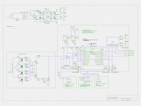
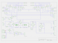
SA2013, SA2014, SA2015 housekeeping circuits
PIC16F690 has been replaced by PIC16F1829 and needs firmware 3.x or higher. Used NTC can be selected in Software: either 2.2k or 10k
WARNING: these circuit are using very high AC voltages and is therefore very dangerous and can be lethal. I am not responsible for any costs, damage and/or injury using these schematics. Do not use this schematics if you do not have the necessary experience and knowledge.
Schematics are free to use only for non commercial DIY projects. The used microcontroller needs a special firmware which is currently non free and not public available.
Have fun, Toni
Attachments
-
 sa2013_mains_control_schematic.png186.7 KB · Views: 856
 -
 sa2013_mains_inrush_schematic.png121.9 KB · Views: 856
 -
 sa2013_output_relais_dual_mono_schematic.png130.1 KB · Views: 823
 -
sa2013_mains_control_schematic.pdf55.6 KB · Views: 240
-
sa2013_mains_inrush_schematic.pdf40.6 KB · Views: 262
-
sa2013_output_relais_dual_mono_schematic.pdf48.5 KB · Views: 266
SA2013, SA2014, SA2015 housekeeping circuits
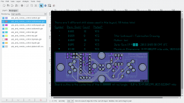
Attached PCB layouts. Gerbers will follow soon.
A note for "sa2013_mains_inrush.pdf": Only single layer pcb needed. The top layer shows the to be soldered short circuit wires.
If you need pcb's and/or a pre programmed pic16f1829 send an email to
Attached PCB layouts. Gerbers will follow soon.
A note for "sa2013_mains_inrush.pdf": Only single layer pcb needed. The top layer shows the to be soldered short circuit wires.
If you need pcb's and/or a pre programmed pic16f1829 send an email to
sa20xx-hk (at) aws-it (dot) at
Have fun, Toni
Attachments
"buy" is the wrong word. It's fee free for your non commercial and private DIY project but currently not publicly available. See email address above.Toni where would we buy the firmware ?
Have fun, Toni
SA2013, SA2014, SA2015 housekeeping circuits
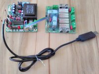
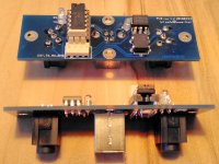
Some pictures of my development sample (you can see some leds and ntc attached for testing)
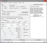
For configuration you need an
Have fun!
Toni
Some pictures of my development sample (you can see some leds and ntc attached for testing)
For configuration you need an
- USB2RS232 serial adapter with TTL level output. You can get such adapters for below 10 $ or 10 EUR.
- and a terminal program:
- Windows: Hyperterminal
- Linux: minicom
Toni
Attachments
Last edited:
SA2013, SA2014, SA2015 housekeeping circuits
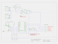
... small board for nerds who often want to reconfigure their mains power on configuration:
... small board for nerds who often want to reconfigure their mains power on configuration:
- remote power via 12V signal
- usb interface for mains control board MCU configuration
Attachments
SA2013, SA2014, SA2015 housekeeping circuits
... the MCP2221 works out of the box but need some fixed configuration otherwise it could be configured to be unusable ...
Using menu "chip access" the settings can be made permanent. Unfortunately the microchip mcp2221 utility only runs under windows ... 🙁
The MCP2221 registers as /dev/ttyACM0 on a modern linux machine
In windows it registers as usb serial port.
BR, Toni
... the MCP2221 works out of the box but need some fixed configuration otherwise it could be configured to be unusable ...
Using menu "chip access" the settings can be made permanent. Unfortunately the microchip mcp2221 utility only runs under windows ... 🙁
The MCP2221 registers as /dev/ttyACM0 on a modern linux machine
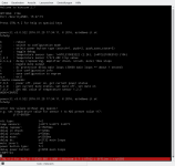
Code:
[630862.959686] usb 4-1: new full-speed USB device number 2 using xhci_hcd
[630863.148435] usb 4-1: New USB device found, idVendor=04d8, idProduct=00dd
[630863.148443] usb 4-1: New USB device strings: Mfr=1, Product=2, SerialNumber=3
[630863.148448] usb 4-1: Product: Power amplifier control v3.0.0
[630863.148452] usb 4-1: Manufacturer: ASTXLabs
[630863.148455] usb 4-1: SerialNumber: 00000001
[630863.152234] hid-generic 0003:04D8:00DD.0003: hiddev0,hidraw2: USB HID v1.11 Device [ASTXLabs Power amplifier control v3.0.0] on usb-0000:0b:00.0-1/input2
[630863.725208] cdc_acm 4-1:1.0: ttyACM0: USB ACM device
[630863.725775] usbcore: registered new interface driver cdc_acm
[630863.725782] cdc_acm: USB Abstract Control Model driver for USB modems and ISDN adapters
toni@tnserver01:~/pcb/audio_power_amplifier/usb_and_remote_control/doc> uname -a
Linux tnserver01 4.1.15-8-default #1 SMP PREEMPT Wed Jan 20 16:41:00 UTC 2016 (0e3b3ab) x86_64 x86_64 x86_64 GNU/LinuxBR, Toni
Attachments
Last edited:
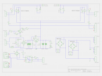
SA2013, SA2014, SA2015 housekeeping circuits
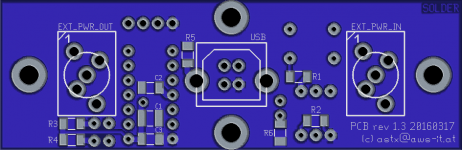
... gerbers for the small usb/remote power pcb ...
Schematics and pcb/gerbers are free to use only for non commercial DIY projects.
Have fun, Toni
... gerbers for the small usb/remote power pcb ...
Schematics and pcb/gerbers are free to use only for non commercial DIY projects.
Have fun, Toni
Attachments
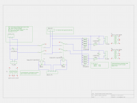
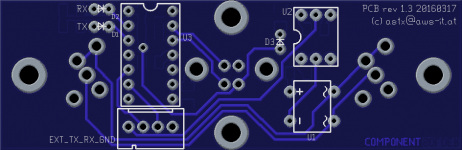
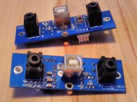
SA2013, SA2014, SA2015 housekeeping circuits
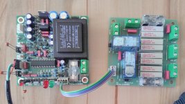
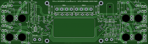
This is the back panel electronics including speaker relais for the 4 channel MOSFET power amplifier...
Schematics and pcb/gerbers are free to use only for non commercial DIY projects.
BR, Toni
This is the back panel electronics including speaker relais for the 4 channel MOSFET power amplifier...
Schematics and pcb/gerbers are free to use only for non commercial DIY projects.
BR, Toni
Attachments
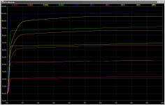
One problem with the DCA data is that at 10mA the device is heating enough to shift the curve. 2mA curves are probably okay.
10mA at 1V is 10mW which means 2C rise for TO92.
If I knew the exact timing of the measurements I could use the thermal response of the BJTs to estimate a fit, but estimations upon estimations is bad for accuracy.
Strangely, the Fairchild model matches the OnSemi data very well at low thermal points. See the attachment. The OnSemi parts have a bit of quasi-saturation which shows you which curves are the real device.
Attachments
One problem with the DCA data is that at 10mA the device is heating enough to shift the curve. 2mA curves are probably okay.
...
If I knew the exact timing of the measurements I could use the thermal response of the BJTs to estimate a fit, but estimations upon estimations is bad for accuracy.
...
Great! Hmm ... some of the DCA sweep parameters can be tuned. I will try to catch the timings with my scope if I find some spare time. Tell me which range, steps and from/to values for which devices are of interest for you ... 🙂
BR, Toni
I don't know if it would be feasible to try and eliminate the thermals through changing the testing parameters, unless they are very flexible and can use a function. The best thing to do may be to reduce testing current by 10, so test at 1mA instead of 10mA. But that would hide quasi-saturation.
More datapoints in general would be useful, because the Vaf can be found in noisy data through averaging. Although I have to convert to CSV by hand so unless that can be automated I don't want to risk carpal tunnel.
More datapoints in general would be useful, because the Vaf can be found in noisy data through averaging. Although I have to convert to CSV by hand so unless that can be automated I don't want to risk carpal tunnel.
- Home
- Amplifiers
- Solid State
- 2stageEF high performance class AB power amp / 200W8R / 400W4R