next round:
R1 = 1k, primary winding shorted, one secondary shorted
To find the ringing I had to look into much higher frequencies, my scope doesn't store anymore at this speed.
Pictures show:
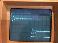
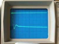
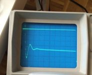
No snubber, only Cx Rs=inf, Rs=100, Rs=33, Rs=0 Ohm
Again, I can dampen the ringing, but I can't eliminate it.
Square wave is 1V/div, Channel 2 is 20mV/div, 0.5us/div#
Did I do it right, this time?
R1 = 1k, primary winding shorted, one secondary shorted
To find the ringing I had to look into much higher frequencies, my scope doesn't store anymore at this speed.
Pictures show:
No snubber, only Cx Rs=inf, Rs=100, Rs=33, Rs=0 Ohm
Again, I can dampen the ringing, but I can't eliminate it.
Square wave is 1V/div, Channel 2 is 20mV/div, 0.5us/div#
Did I do it right, this time?
Attachments
It's surprising and suspicious that you only set the knob of your 20-turn trimmer potentiometer to resistance values that happen to correspond to standard E6 values of fixed resistors. Don't do that! The whole purpose of a 20-turn trimmer is to give you incredibly smooth and fine-grained control. Start the knob at max-resistance and slooooooowly wind it down to lower and lower resistance, while watching the scope face. When the waveform's second lumpity bumpity completely flattens out (see yellow arrow in Quasimodo design note Fig.1), stop winding it down. Yank the trimmer out of the test fixture and measure it with your 3.5 digit DMM on ohmmeter setting.
I printed your scope photos onto sheepskin parchment and took them out into the woods. I smeared them with ceremonial oil and set them on fire while praying to Ozymandias and smoldering the ceremonial herbs. I received a prophesy that (a) your transformer's leakage inductance is probably in the neighborhood of 270 nanohenries; (b) if you continue using Cx=10nF and Cs=150nF then probably the waveform's second lumpity bumpity will disappear when Rsnub=14 ohms. Now you should know that Ozymandias is sometimes wrong, and she never makes a guarantee, only a suggestion. But it's worth noting.
When Quasimodo gives newcomers a surprising result measuring a transformer, I usually recommend stepping back and using QM on known inductors (whose answers we can calculate in advance, thus we know what Quasimodo should report).
Please see post #257 and post #487 for ideas about how to certify a Quasimodo (even an ExtraLight) using a fixed inductor of known value.
While you're ordering a 270 nanohenry, ±5% inductor from your electronic parts distributor, go ahead and also order a 20 turn 1K trimmer and a 20 turn 100 ohm trimmer.
Thanks for going through the ordeal with all the preparation, burning and praying, I really appreciate that. Apart from the mystic figures I presume you have received the blessing that my little pictures are acceptable for worship given the ritual objects I have consulted: tranny, caps, etc.
I have to share a secret, though, and I beseech you to spare me from the stake: this isn't a 20-turn pot, it is a 500Ohm trimmer, parallelled with a 100 Ohm E6 resistor.
Its, with the rest, what I had in the box. (Btw 304 Ohm is probably E192). Admittedly, it is difficult to tune this at the low values in question.
Also in the box I have two 22 Ohm resistors, and I find that with 22 and 11 Ohms for Rs the lumpity bumpity comes back up nearer towards the trace I show for Rs=0. This isn't meant to question Ozymandias, of course.
My whole test rig involves lots of aligator clips, unshielded cables and stuff. Given the high frequencies, I guess I should start firming up. Maybe I find a 20-turn trimpot on the way.
In your note I can't find traces beyond optimal Rs. Is my observation valid that with Rs = 0 the ringing is back, but with slightly different frequency?
Oh, and would you suggest other Cx and Cs values for my case?
Last edited:
When Rs=0 the secondary circuit does not contain any mechanism to dissipate the oscillatory energy. There are three energy storage elements but no energy dissipation elements. There is an inductor (transformer leakage inductance), a capacitor Cx, and a second capacitor Cs. What do YOU think the damping factor might be?
For those who wish to study further, I have supplied an LTSPICE circuit simulation testbench. It is shown in post #1 of the Cheapomodo thread. Run some LTSPICE simulations using a wide variety of Rs values, corresponding to whatever damping factors you like. (Equation A.10 on page 17 shows how to convert back and forth between damping factor and Rs value). Print out the results and save them in your laboratory notebook for reference, in case you want a quick reminder two or three years from now.
Several dozen diyAudio members have successfully built their own Quasimodo jigs and used it to snub their own transformers. A handful of them wanted additional reassurance that their jig and their oscilloscope were trustworthy, so I suggested they follow the certification & calibration protocol mentioned in posts #257 and #487. This gave the "Eureka!" breakthrough they sought, and now they are happy and satisfied Quasimodo users.
However if you require individual hand-holding and tutoring on how to debug your Quasimodo, and how to use it, and how to interpret the results, and "does this look good to people who know a lot more than me?", I suggest you start your own thread with a provocative and eye-catching title, maybe like
- Help! Quasimodo is kicking my a** HARD and I have no idea what to try next!?
- Too much math in the "No Math" Quasimodo and I'm totally lost, help me Obi-Wan Kenobi!
- Help! All I want to do is snubber my Trafo, but my feces-rigged QuasimodoEL won't cooperate
Here are some 270 nanohenry fixed inductors from European distributors:
I suspect that 5% tolerance inductors might be available from the same suppliers too, needing just a bit more searching. Left as an exercise for the reader.
I suspect that 5% tolerance inductors might be available from the same suppliers too, needing just a bit more searching. Left as an exercise for the reader.
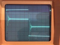
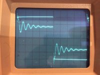
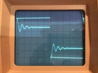
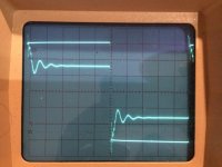
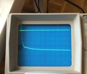
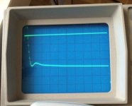
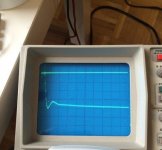
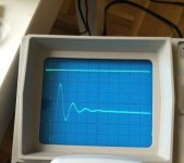
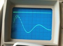
For those interested how pictures look like when using a 6Vpp square wave generator (and better wiring than before) injecting current into a Toroidy 400VA 2x18V transformer via a 1kOhm resistor, here they are.
5mV/div, 0.5us/div, Cx=10nF, Cs=150nF,
the Rs values measured for each trace are
47.5, 38.0, 32.3, 13.3, 11.7, 9.6, 1.5 Ohm
Note, however, that the DMM measures a closed circuit as 1.5 and a 10Ohm resistor as 11.4 Ohm.
The last picture shows how a vanishing Rs results in a ringing with much lower resonance frequency. I presume in a regular Quasimodo you can't see that as the dang from a charged 10nF capacitor goes pfffft, when paralleled with an empty 150nF cap.
Attachments
Don't forget that your QMExtraLight approximate "current source" stimulus has a Norton equivalent resistance of 1K, between the oscillatory node and AC ground. Thus the 1K resistor dissipates some of the oscillatory energy, so its resistance is effectively in parallel with Rs as far as damping is concerned. This is more and more important when Rs grows to approach 1K; or, stated the other way, it is more and more negligible when Rs falls (Rs << 1K).
Quasimodo people and Cheapomodo people see the same thing you see when Rs approaches zero. LTSPICE simulation people see it too. The differential equations are the same in all three cases, and they don't tell lies. When Rs=0 the Cx/Cs ratio just acts as a (capacitive) voltage divider at high frequencies; it affects the amplitude of the bell-ringing whack, but not the risetime. The ringing is still visible on even the crappiest scopes with the crummiest vertical gain (0.5V per division?!!?)
Quasimodo people and Cheapomodo people see the same thing you see when Rs approaches zero. LTSPICE simulation people see it too. The differential equations are the same in all three cases, and they don't tell lies. When Rs=0 the Cx/Cs ratio just acts as a (capacitive) voltage divider at high frequencies; it affects the amplitude of the bell-ringing whack, but not the risetime. The ringing is still visible on even the crappiest scopes with the crummiest vertical gain (0.5V per division?!!?)
Last edited:
I apoligize for asking this stupid question.
There is talk of a design note with pages and figures.
Where is it?
There is talk of a design note with pages and figures.
Where is it?
1st post in the thread
I apoligize for asking this stupid question.
There is talk of a design note with pages and figures.
Where is it?
I really was a stupid question, particularly given your answer.
But at least I found it on my own.
So now let me make a contribution to the group.
I snubbed a very expensive tube preamp B plus power supply.
This is incredibly audible power supply. You can hear any change.
I listened as I snubbed.
It is somewhat of a mixed bag because even though the snubber cleans up the background noise it also blunts dynamics somewhat.
I think you are better off slightly undersnubbed.
The smaller cap across the secondary is very audible. I wound up using an RTI teflon cap.
I experimented using all types of larger caps with the resistor. I preferred the carbon film types as they were slightly warmer--radio shack.
I also tried using very large ceramic caps for the larger caps. They were the cleanest by far but the resulting sound was more shut in, less acoustic.
The larger cap really cleaned up the midrange when tuned properly. If it was too large it compromised openness and dynamics.
I went with Teflon caps in both positions ultimately.
By the way, I was already using expensive soft recovery rectifiers so its not overkill to use them and a snubber.
Both caps is far better than only one from a listening standpoint.
I wish one of you smart guys could tell me what is the ultimate resulting waveform.
Is it better to critically damp at 1 or are you better off overdamping?
I have found as you keep lowering the resistor you eventually reach a point where you create more problems than you solve.
What is the perfect waveform?
You snubbed the transformer secondary by ear without observing the waveform on an oscilloscope ??!? Not even one of those 30 dollar build-it-yourself oscilloscope kits from eBay ??!?
Wow.
There is no way to know what your final secondary waveform (@ the instant of diode shutoff) might be, without measuring it. The only statement anyone can make with certainty is: your brain+ears like it. Maybe other people's brain+ears will agree, maybe not. There is no way to know with certainty whether your brain+ears prefers underdamped ringing (zeta < 1.0), critically damped non-ringing (zeta = 1.0), or overdamped non-ringing (zeta > 1.0).
I'll bet you tried fewer than 50 different sets of component values in your listening tests; each test takes a LONG time and I'll bet you didn't spend more than two weeks testing. So that might mean that you've accidentally skipped over a different set of component values which your brain+ears might like even better. That's one slight advantage of a 20-turn potentiometer and a scope waveform display: you can try thousands of component values in three minutes as you sloooooowly dial the pot shaft. But hey, you got results that thrill and delight you, so to heck with criticism from armchair quarterbacks.
Congratulations!
You may wish to write up a little 3 page document "How I snubbered my very expensive tube preamp by ear, with no oscilloscope at all, and what a giant improvement it made!" Others might wish to follow in your footsteps. If you put this document here on diyAudio, start a brand new thread and give it a descriptive & provocative title that people can find easily.
*edit- I will try to get a copy of your post to Morgan Jones, the valve amplifier handbook author. He also wrote an article in Linear Audio volume 5 about "Snubbering: Best Practices" for valve equipment.
Last edited:
Hello Mark.There is no way to know with certainty whether your brain+ears prefers underdamped ringing (zeta < 1.0), critically damped non-ringing (zeta = 1.0), or overdamped non-ringing (zeta > 1.0).
.....one slight advantage of a 20-turn potentiometer and a scope waveform display: you can try thousands of component values in three minutes as you sloooooowly dial the pot shaft.
Have you tried this sweeping of resistor value and correlated changes in system sound ?.
Dan.
Last edited:
Unfortunately listening tests require several orders of magnitude more time, than bench tests with scopes require. On the other hand, nobody can prevent you from making an attempt. Feel free to try it!
I will do so when I get around to trying you jig/tester.Unfortunately listening tests require several orders of magnitude more time, than bench tests with scopes require. On the other hand, nobody can prevent you from making an attempt. Feel free to try it!
Did anybody take a listen to zeta << 1.0/zeta < 1.0/zeta = 1.0/zeta > 1.0/zeta >> 1.0 ?.
Dan.
Max Headroom,
Have you built yourself a Quasimodo or CheapoModo yet? My decrepit old filing system indicates that you once inquired, but ultimately decided not to buy a PCB + kit_of_all_parts. In the months and years that followed, did you ever gather the parts and assemble one yourself? Either QM or CM? Have you experimented with Quasimodo ExtraLight, which needs no PCB and no 555 chip and no power supply at all?
FWIW, the author of post #777 in this thread may have an extra QMV4 kit to sell, and accepts PayPal.
Hi Mark.
No I have not built or cobbled a Quasimodo or CheapoModo yet....but I will.
My question was just a query of if you have noted audible effects of various degrees of damping.
Dan.
No I have not built or cobbled a Quasimodo or CheapoModo yet....but I will.
My question was just a query of if you have noted audible effects of various degrees of damping.
Dan.
Years ago, there was an article put up here on the now defunct 'http://mitglied.multimania.de' site by a guy called Promitheus and re-introduced an old idea found by an Andrew Nehan in the old Radiotron Designer Handbook and the RSGB Handbook - it's about adding a capacitor across the secondary windings of a transformer in parallel with the bridge and power caps - the description says that 'the first thing you hear is a better sense of bass, faster transients and a sense of clearness'
I've been doing this for years and it's a right royal PIA because using PP or styrene caps still means the value has to be just right for it to work at all and you end up measuring the caps and talking about less than 10s of pF, and lower for low current transformers like those in cd players for example.
I got used to doing it (like a pastime instead of Sudoku puzzles, pcb layours, etc) and if careful, you can quite dramatically change to whole freq response - it's pretty easy with the 300va Txrs in an F5 for example - I think Jack Walton showed a chart about this a few years ago, too
No one seems to know how it works - it doesn't seem to relate to the 'Haggerman snubbers approach that we're using here with your 'bell-ringer' system and it seems to have disappeared from the diyAudio archives - plus, I can't find it in the RSGB Handbook anywhere -
Anyone ever heard of this from the old days of 'ham radio'?
Congratulations!
You may wish to write up a little 3 page document[/I]
А straight answer is a lot less fun than plastering down the sarcasm, but indeed: is there a correlation between best perceived sound and the amount of damping? Cause if there isn't...
I spent a lot of time trying to trace why I had overshoot and mild oscillation in an amplifier from a renowned designer. Only AFTER I removed the MKP across the ~~ of the rectifier did the amp start to play properly. I added a 100r+100nF MKT to replace the MKP.Years ago, there was an article put up here on the now defunct 'http://mitglied.multimania.de' site by a guy called Promitheus and re-introduced an old idea found by an Andrew Nehan in the old Radiotron Designer Handbook and the RSGB Handbook - it's about adding a capacitor across the secondary windings of a transformer in parallel with the bridge and power caps - the description says that 'the first thing you hear is a better sense of bass, faster transients and a sense of clearness'
I've been doing this for years and it's a right royal PIA because using PP or styrene caps still means the value has to be just right for it to work at all and you end up measuring the caps and talking about less than 10s of pF, and lower for low current transformers like those in cd players for example.
I got used to doing it (like a pastime instead of Sudoku puzzles, pcb layours, etc) and if careful, you can quite dramatically change to whole freq response - it's pretty easy with the 300va Txrs in an F5 for example - I think Jack Walton showed a chart about this a few years ago, too
No one seems to know how it works - it doesn't seem to relate to the 'Haggerman snubbers approach that we're using here with your 'bell-ringer' system and it seems to have disappeared from the diyAudio archives - plus, I can't find it in the RSGB Handbook anywhere -
Anyone ever heard of this from the old days of 'ham radio'?
The extra lower frequency ringing in the PSU was affecting the HF stability of the amplifier.
It turned out that the amplifier did have an extreme sensitvity to peripherals and caught fire in front of me while playing music at sensible levels. I did not rebuild it.
Overshoot on fast music signals gives an apparent heightend level of treble that is not present in the original signal.
Last edited:
- Home
- Amplifiers
- Power Supplies
- Simple, no-math transformer snubber using Quasimodo test-jig