That was a bad joke, sorry. look for posts by a certain someone earlier in the thread.
Not sure if that was aimed at me, but I'll throw you a wink anyways [emoji6]
wesayso,
Its your operation and hard work that already show some very impressive results, lot of users accept SRC distortion so think me shall back off a bit even reason was meant to improve measurements results and plots of your work a bit further.
bushmeister,
Notice target is flat so if down the road under listening it gets too hot attach a 5 minute operation into REW PEQ container that with 11x Q=1 high shelving filters give very close to original B&K curve starting downward tilt at 400Hz.
Attachments
Notice target is flat so if down the road under listening it gets too hot attach a 5 minute operation into REW PEQ container that with 11x Q=1 high shelving filters give very close to original B&K curve starting downward tilt at 400Hz.
Interesting to see an implementation of that curve. Nice.
Another alternative is 1.1khz hinge point an 'linear' attenuation at -1.5db/octave up to the highest you can. Work well with my monitor (direct radiator mid/tweeter).
When i say linear i really mean it so it is not easily implemented using shelf filter or even graphical (rare are the graphical eq which are not in fact bell eq stacked in serie so they never end as a linear attenuation general profile), my dsp allow for that (in Lake you have 'Mesa eq' which give 'linear' target when used as graphical eq).
For src what do you use guys? Some dedicated plug ins or software or 'regular' functions in software? Some are better than others. 😉
Last edited:
No. Never.Please show a waterfall plot of the early signal of your speaker to compare.
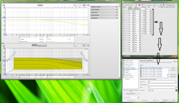
Use settings like these:

These are measurements in room, try and top them... Can you?
Not sure if that was aimed at me, but I'll throw you a wink anyways [emoji6]
Hahaha, no Nate, it certainly wasn't directed at you. These "demo" results (which can be improved on) are what I mean by using frequency dependent windows with a short length. Correcting to minimum phase behavior. In my opinion these are the things needed to get good sound with FIR filters. More often than not things get worse by using "standard" solutions. 🙂
Nothing gets "hammered" into shape, we're using feathers here 😉.
The acoustic lowpass of second order is wrong, because its time error must be equalized by FIR filters. A good driver with shielded pole core does not distort much, hence no backend lowpass is needed. But if you think, that it is needed, then you should dig up up the old research done for bass-reflex ports, about how nonlinear air compression is, depending on SPL and frequency, and how turbulence at hard edges adds to that nonlinearity. No simulations please. It may be difficult computing turbulence in the brain, but if you cannot, then all you have is 131 pages of wank.
Hope this can help in that pretty sure that when speaker was planned it was calculated that either woofer injection ports position should be placed in the correct position for timing relative to tweeter, nor should injection ports acoustic low pass be the natural precision slope for intended XO point but just have enough bandwidth. Planned from start was build would need DSP steering and this gives freedom to best placement of injection ports in other regards on a low cost consumer horn that is really not brought to market in first place for be used as a point source horn.
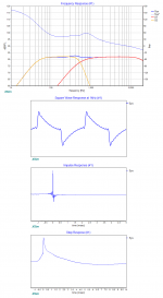
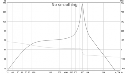
Therefor think you too fast when complaining about acoustic low pass of second order is wrong because wesayso make some FIR cleanup. Planned acoustic low pass running minimum phase XO is not 2nd order but BW4, and filter is Harsch concept which have BS2 high pass slope for tweeter. In first picture Harsch XO can be seen and with correct set delay for tweeter will give a nice transient response compared other minimum phase filters. Also EQ is needed because woofers acoustic 4th order symmetric bandpass have huge resonance ala what is seen picture two.
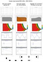
Picture 3 is to show how a minimum phase XO point or should we say stop bands or high Q amplitude changes adds ringing to waterfall. As seen in first column a one-way very wideband driver throw very clean waterfall and waveform, where column two show with a LR4 XO example and the ringing plus waveform distortion it adds. In column three is a FIR filter with nothing that the inverse phase correction to clean exactly the LR4 XO distortion in column two. This FIR filter is speaker correction but wesayso use DRC which handle room correction too plus think he is very good setup far field data at listening position.
Attachments
Last edited:
Yep!!!
Amazing results - bearing in mind these measurements are taken 2.5m away from the speaker, in my study at the LP. 😀
I have been away for a bit and see the great progress. Nice!
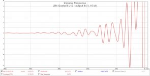
OK guys - after you all noticed the digital artifacts from the sample rate conversions that weren't optimized a few posts ago, I started thinking about my digital source and processing a little more.
I currently use a PC source with foobar and my source material is nearly all 44.1, 16 bit. I output this material via USB into a Gustard U12, then via AES/EBU into the digital input of my miniDSP 4x10 Hd with 96Khz plugin.
I am aware the miniDSP 4x10 HD, re-samples all digital inputs to 96KHz, 24 bit depth internally.
The Gustard U12 uses XMOS - U8 chip, Two 0.1PPM precision crystal 45.1584M 49.1520M, nice power supply etc. And is highly regarded.
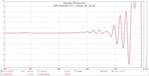
So I am wondering if it is better to get the Gustard U12 to do the sample rate conversion before the 4x10HD. i.e. Change the U12 to output 96KHz 24bit straight into the 4x10 HD, so the miniDSP doesn't have to do any internal sample rate conversion.
To explore this, I tried looking at the impulse responses with the two set ups.
I am aware this is a little off topic, but would like to get this side of things right given the potential of the Xbush speakers. Note - these measurements were done using the prestige speakers.
Does anyone think there is a significant difference here?!?
Thanks for your advice.
I currently use a PC source with foobar and my source material is nearly all 44.1, 16 bit. I output this material via USB into a Gustard U12, then via AES/EBU into the digital input of my miniDSP 4x10 Hd with 96Khz plugin.
I am aware the miniDSP 4x10 HD, re-samples all digital inputs to 96KHz, 24 bit depth internally.
The Gustard U12 uses XMOS - U8 chip, Two 0.1PPM precision crystal 45.1584M 49.1520M, nice power supply etc. And is highly regarded.
So I am wondering if it is better to get the Gustard U12 to do the sample rate conversion before the 4x10HD. i.e. Change the U12 to output 96KHz 24bit straight into the 4x10 HD, so the miniDSP doesn't have to do any internal sample rate conversion.
To explore this, I tried looking at the impulse responses with the two set ups.
I am aware this is a little off topic, but would like to get this side of things right given the potential of the Xbush speakers. Note - these measurements were done using the prestige speakers.
Does anyone think there is a significant difference here?!?
Thanks for your advice.
Attachments
Last edited:
OK guys - after you all noticed the digital artifacts from the sample rate conversions that weren't optimized a few posts ago, I started thinking about my digital source and processing a little more.
I currently use a PC source with foobar and my source material is nearly all 44.1, 16 bit. I output this material via USB into a Gustard U12, then via AES/EBU into the digital input of my miniDSP 4x10 Hd with 96hz plugin.
I am aware the miniDSP 4x10 HD, re-samples all digital inputs to 96Hz, 24 bit depth internally.
The Gustard U12 uses XMOS - U8 chip, Two 0.1PPM precision crystal 45.1584M 49.1520M, nice power supply etc. And is highly regarded.
So I am wondering if it is better to get the Gustard U12 to do the sample rate conversion before the 4x10HD. i.e. Change the U12 to output 96Hz 24bit straight into the 4x10 HD, so the miniDSP doesn't have to do any internal sample rate conversion.
To explore this, I tried looking at the impluse responses with the two set ups.
I am aware this is a little off topic, but would like to get this side of things right given the potential of the Xbush speakers. Note - these measurements were done using the prestige speakers.
Does anyone think there is a significant difference here?!?
Thanks for your advice.
You forgot the K-hz😀
Bushmeister, loop back the output of the mini DSP to the line in with a cable. That way you're only looking at the signal itself and the components involved, a speaker has way more problems than that.
A loop back of my PC to DAC to line in looks like this in APL_TDA:

In REW you can closely examine the differences with a loop back like this which should present you with the cleanest IR. The 16 bit option is always wrong. Even 44100/24 bit will be way better for headroom. From that point on it depends on the up-sampling. Which device does the best job, do we even need up-sampling... etc...
I have an up-sampling DAC. I feed it 44100/24 bit for now, until I find something better.
You've got to realize the IR REW presents is just a chosen form of presentation. Sort of like a rendering. There is much more info in the IR than you see in that standard representation. Do not go past that fact. It's the reason for all the different looks on that same piece of data. The waterfall, the Wavelet etc.
It's all the same data looked at in another way.
A loop back of my PC to DAC to line in looks like this in APL_TDA:
In REW you can closely examine the differences with a loop back like this which should present you with the cleanest IR. The 16 bit option is always wrong. Even 44100/24 bit will be way better for headroom. From that point on it depends on the up-sampling. Which device does the best job, do we even need up-sampling... etc...
I have an up-sampling DAC. I feed it 44100/24 bit for now, until I find something better.
You've got to realize the IR REW presents is just a chosen form of presentation. Sort of like a rendering. There is much more info in the IR than you see in that standard representation. Do not go past that fact. It's the reason for all the different looks on that same piece of data. The waterfall, the Wavelet etc.
It's all the same data looked at in another way.
Last edited:
Thanks wesayso - I was hoping you would answer!
That is incredibly helpful - I am fairly new to this digital age - my previously sealed three ways have an active analogue crossover, and I even listen to vinyl on them at times......!
I will get playing.
Thanks.
That is incredibly helpful - I am fairly new to this digital age - my previously sealed three ways have an active analogue crossover, and I even listen to vinyl on them at times......!
I will get playing.
Thanks.
Minidsp is really upsampling everything digital?
Hmmm. If i where you and if you don't mind latency (and have enough power with your pc) you should have it done before the soundcards, just after the player (or inside it) with a dedicated solution. Should be better than what is inside the minidsp.
Hmmm. If i where you and if you don't mind latency (and have enough power with your pc) you should have it done before the soundcards, just after the player (or inside it) with a dedicated solution. Should be better than what is inside the minidsp.
Minidsp is really upsampling everything digital?
Hmmm. If i where you and if you don't mind latency (and have enough power with your pc) you should have it done before the soundcards, just after the player (or inside it) with a dedicated solution. Should be better than what is inside the minidsp.
Only one way to find out! Don't assume, measure! 😀
Don't assume, measure!
You are right Ronald but for that i've already done measurement from my side so i know a dedicated src solution is better than one 'off the shelf' included in a (generic) chip. Well the one i have in mind i should say... 😉
OT: I'll answer latter this evening to you Ronald. Anyway thank you!
Last edited:
So what would you do if you have a DAC that up-samples everything to 24/192. Yet the optical input is 24/96 max. I figured I was better off with one upsampling stage. My ears seem to agree... just curious 🙂.
(my DAC being the Musical Fidelity M1 DAC)
(my DAC being the Musical Fidelity M1 DAC)
Last edited:
... change DAC! 😉
In this situation you are stuck. Just hope it's a good dedicated src chip used in the dac.
That is one of the reason i keep on advice to use pro gear: they usually give you the choice or just do one thing (usually right).
In this situation you are stuck. Just hope it's a good dedicated src chip used in the dac.
That is one of the reason i keep on advice to use pro gear: they usually give you the choice or just do one thing (usually right).
BYRTT, the amount of equalizing you use is an indicator that there is something wrong with concept. Bass-reflex needs port area of at least one tenth of diaphragm area in order to have low distortion. Altho bass-reflex ports have low bandwidth thus few intermodulation. Small Synergy ports transmit more than two octaves, so when air distortion starts, there occurs intermodulation, too. There occurs much Doppler distortion, too, because Doppler depends on speed only, of air gushing thru a port just as well as of a moving diaphragm.
There is at least one better concept for high directionality, one by Follgott, using Horbach-Keele FIR filters, a tweeter horn and two direct-radiating ways in a symmetrical arrangement.
There is at least one better concept for high directionality, one by Follgott, using Horbach-Keele FIR filters, a tweeter horn and two direct-radiating ways in a symmetrical arrangement.
There is at least one better concept for high directionality, one by Follgott, using Horbach-Keele FIR filters, a tweeter horn and two direct-radiating ways in a symmetrical arrangement.
So start a thread on that rather than pollute this one!
So start a thread on that rather than pollute this one!
...or Grasso789 could read the answer already given (post #1299) ! But then after don't say/write things like that:
I have a little grump with FIR, which i consider faking.
Because without FIR Hornbach/Keele method can't work!

So if your goal is just troll, please give up and give us a rest.
Last edited:
- Home
- Loudspeakers
- Multi-Way
- A Bookshelf Multi-Way Point-Source Horn