That will depend on the Idss of the jfets, the jfet idle current with degeneration, and the output fet Vgs at 1A. It is a pretty easy calculation:
Rdrain_load = Vgs_1A/Ijfet
Thanks for you answers ! 🙂
Hello lhquam. Will the results change when Rload is replaced with an electrical model of a loudspeaker; like an 8 Ohm woofer?.I have updated my schematic of post #218 using information gained from the 6Moons photos and everything simulates fairly well.
I estimate the open-loop gain of the jfet and output fet stages into an 8 Ohm load to be 42dB with all feedback removed. This was measured as the V(Out+,Out-)/V(gates,fbnode), where gates is the jget gate node, and fbnode is the wiper of potentiometer P3. With a closed-loop gain of 14dB that means that there is 28dB of negative feedback, which is a huge feedback factor. Perhaps I am incorrectly estimating the open-loop gain, but that gain factor is fairly consistent with the F5.
Reactive loads will cause a frequency dependent change in impedance and change the distortion characteristics. With the high damping factor, the output voltage will not change much.Hello lhquam. Will the results change when Rload is replaced with an electrical model of a loudspeaker; like an 8 Ohm woofer?.
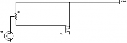
tricky arrangement to achieve gate resistance, biasing, and loading of jfet input (three birds with one stone) and calling it no gate resistance (I can think of an arrangement to achieve this)
Ok here is my 3 birds with one stone trick, before someone else claims it.
I have plenty more dumb ideas but they are top secret muah hahahaha
Attachments
Ok here is my 3 birds with one stone trick, before someone else claims it.
I have plenty more dumb ideas but they are top secret muah hahahaha
Very clever -- and it should work just fine if the leftover resistance is in a reasonable range.
Last edited:
A 1k multiturn trimpot should do the trick, assuming around 8mA through jfet, that should allow 700 Ohms to 800 Ohms for gate resistance depending on your bias point.Very clever -- and it should work just fine of the leftover resistance is in a reasonable range.
You could certainly try lower maybe a 500 Ohm multiturn trimpot, but you'll have less gate resistance
pico - you're going to make fuzz box ........ or Eq guitar device ?

Hahahaha.
Naah, just need to exercise a couple of brain cells. I'm not giving away all my tricks. Hahahaha
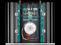
If we look at picture published on 6 moons we can clearly see that toroid main power transformer have no center tap on both secondaries coils ,
there is only four wires for primary side (120VAC+120VAC ) with series connected thermistor in between them ,and in that way that F7 amp is connected for operation on 240VAC main voltage,
and what`s left is only four wires going from two independent secondaries to two Greatz rectifiers ,
Those four green same values wire-wound power resistors on PSU-PCB are ,
-part of CRC-PSU filters
-or for making of two independent virtual or floating grounds points ,which I think that they really are ,
there is one more thermistor on PSU-PCB which is connected in between main earth wire(chassis) and amplifier ground lines for safety reason .
Attachments
Last edited:

It seems to me the earth pin on the mains are the only connection to the chassis - safety ground that is.
The input RCA sockets are also isolated from the chassis.
The virtual/floating grounds as described by Banat are of course also isolated from the chassis.
In this way currents will not flow in the chassis at all. This is important from an EMC point of view. Currents originating from the amplifier itself will not travel on the chassis, and hence not radiate to the outer world. In the same manner, RF picked up by the chassis will not end up in the amplifying circuitry.
It looks to me like one secondary is for V+ and the other for V-. Each secondary drives a bridge rectifier and a CRCC filter. It would be similar to this schematic from the F6 BAF talk, except with 2 caps per channel for each rail:
I don`t exclude possibility that F7-PSU is done in same way as F6-PSU ,
but maybe this F7-PSU is done different , with two independent virtual grounds points ,
where each amp ground points is returned to associated virtual ground point ,including loudspeaker ground point (-) ,
BTW , my kitchen 24/7 Revox-A78 a/B class amp PSU is done in that way .
Attachments

Last edited:
I still see the thermistor linking star ground to chassis ground
Yes , it must be installed there for safety reason .
Last edited:
Uh-hmmm. Well, I still stand by what I wrote regarding RF contamination and ground, as a principle.
PCB ground tracks/ground planes WILL have potential differences, and connecting ground to the chassis at two different places WILL make sure this difference will exist on the metal chassis. And vice versa. RF from the outside will thus be transferred to the inside by this mechanism.
I really enjoyed reading this thread tonight. It was like "Watching the Detectives". Good work Boyz
I don`t exclude possibility that F7-PSU is done in same way as F6-PSU ,
but maybe this F7-PSU is done different , with two independent virtual grounds points ,
where each amp ground points is returned to associated virtual ground point ,including loudspeaker ground point (-) ,
BTW , my kitchen 24/7 Revox-A78 a/B class amp PSU is done in that way .
If done this way the only chassis connection per audio PCB is via the thermistor. The screen of the input cable will be connected to the virtual ground. Minus pole to the loudspeaker is isolated from the chassis and is at virtual ground.
Yes , it must be installed there for safety reason .
Yeah basic stuff, consistent with all the firstwatt amps.
If done this way the only chassis connection per audio PCB is via the thermistor. The screen of the input cable will be connected to the virtual ground. Minus pole to the loudspeaker is isolated from the chassis and is at virtual ground.
Yes ,that`s right ,
it`s same chassis grounding scheme as for F6 ,except that now we have amps virtual two grounding points done via four reference same value power resistors , which in case that some output power device fail short in the same time limits DC current on LS , virtually protecting LS coil from damage.
too much guessing
whatever - from pictures at 6moon , it's visible that xformer is regular 2 x 18Vac jobie
whatever - from pictures at 6moon , it's visible that xformer is regular 2 x 18Vac jobie
too much guessing
whatever - from pictures at 6moon , it's visible that xformer is regular 2 x 18Vac jobie
Yes I agree is to much guessing ,
that have to be stopped by presenting original F7 scheme , done by guess who ? 😀
Edit , now I see that white label on PT where is fuzzily signed that secondary is 2 x 18 VAC .
Last edited:
- Home
- Amplifiers
- Pass Labs
- First Watt F7 review