I generally have had best luck when I get the ports as close in as I can get them -- which is how I ended up using 2" mid drivers.
My take after reading all the patents was that closer is better. All the verbiage about critical distances is just to bolster the patent claims to make them admissible.
I think that you must be out of the FORTRAN loop. ".h" files are for C, FORTRAN uses ".inc".
Some of my code uses mixed development from both C and FORTRAN (C compiled .dll's linked to FORTRAN).
I stopped upgrading to newer versions of the dev packages some time ago so did not realize all this ended up as a big MS product.
no good for a synergy ? smooth ! You mean the 1.4 serie sounds like the 2.0 ?
Yes big distorsions in the highs with the 20xx series ! Maybe the same with the 1.4", I don't know, but I like the diving curve...
Yes big distorsions in the highs with the 20xx series ! Maybe the same with the 1.4", I don't know, but I like the diving curve...
Last edited:
My take after reading all the patents was that closer is better. All the verbiage about critical distances is just to bolster the patent claims to make them admissible.
closer is better if you want the highest possible crossover frequency to the CD;
If you do "just close enough" to support a moderate to low crossover frequency, e.g. around 1 Khz, then you get maximum benefit from the acoustic low pass filtering of the mids' bandpass chambers.
Its also clear that the mid port location is critical to determining the amount of crossover phase shift required to time align the mids with the CD and this matters a great deal if you are doing a passive crossover (I'm not.).
I don't want to get into patent analysis out of respect for the inventor but I will pose one question. Is it possible to design a multi-entrant horn under the original Unity horn patent without violating the Synergy patent? One would think not from a reading of the first claim of the Synergy patent, except for the fact that the Synergy horn patent was preceded by the Unity horn patent. It might be that a horn designed according to the as close as possible rule needs license only under the Unity patent and such a license might be easier to obtain.
2.0 in this case are 1.4+adapterno good for a synergy ? smooth ! You mean the 1.4 serie sounds like the 2.0 ?
The 18 sound, having a larger 3" diaphragm, would have less distortion than the JBL 2426J.JBL 2426J (16 ohms) : even wider than the 8 ohms version. Still 1" ! Clean from 800 Hz to 16/18 K Hz ?
or 18Sound http://www.teamaudio.fr/media/catalog/product/datasheet/eighteen_sound/NSD1480N-8.pdf
?
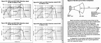
The JBL 2426J is typical of most 1.75 to 2" diaphragm compression drivers, with 2.56 watt input it has rising distortion reaching 40% second harmonic distortion at 10 kHz.
This is why I'm presently so interested in the small "full range" speakers like the 3.5" Tymphony TC9FD, it has only a fraction of the distortion of a compression driver at similar output levels, and is capable of another octave lower than a 3" diaphragm compression driver.
Whether a throat arrangement for the TC9FD that allows uniform HF dispersion without reducing the output is possible is what I'm going to work on next.
The JBL Technical Notes Volume 1, Number 8, though 25 years old, is very informative regarding the reasons why all high frequency compression driver/horns have such awful distortion above fractions of a watt:
JBL Technical Notes Volume 1 Number 8
Art
Attachments
nc535 - I think that you see exactly the same issues that I saw. One cannot have a claim that is encompassed by a prior patent.
If you need a volunteer to help create a (robust) installer then I would be happy to donate some time (nb am a developer by day, albeit 100% *nix these days, so might be somewhat familiar with some of the issues).There are programs can trace all DLL dependencies and these helped me before, but they can be tedious to use.
The 18 sound, having a larger 3" diaphragm, would have less distortion than the JBL 2426J.
The JBL 2426J is typical of most 1.75 to 2" diaphragm compression drivers, with 2.56 watt input it has rising distortion reaching 40% second harmonic distortion at 10 kHz.
This is why I'm presently so interested in the small "full range" speakers like the 3.5" Tymphony TC9FD, it has only a fraction of the distortion of a compression driver at similar output levels, and is capable of another octave lower than a 3" diaphragm compression driver.
Whether a throat arrangement for the TC9FD that allows uniform HF dispersion without reducing the output is possible is what I'm going to work on next.
The JBL Technical Notes Volume 1, Number 8, though 25 years old, is very informative regarding the reasons why all high frequency compression driver/horns have such awful distortion above fractions of a watt:
JBL Technical Notes Volume 1 Number 8
Art
Weltersys,
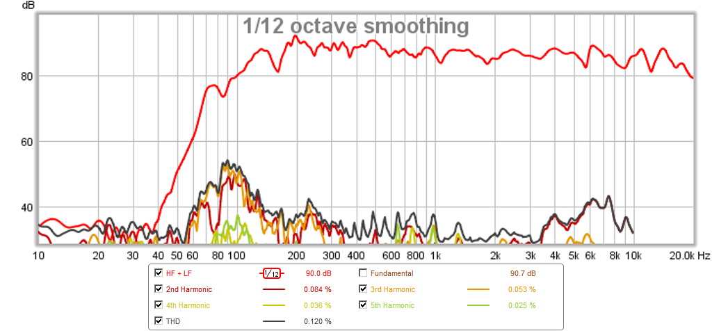
That TC9FD may surprise you. Even EQ'd flat response it had some decent lower distortion in my Trynergy. This required a 12dB Q=0.5 high shelf at 3.5kHz if I remember correctly. It sounded spectacular and not even having to qualify (for a $12 driver). Sounded spectacular, period.
http://www.diyaudio.com/forums/full...g-trynergy-full-range-tractrix-synergy-2.html
Response here is combined with bass woofers - TC9 output is XO at 400Hz.
Last edited:
Pattern measurement consistency
Something that occurred to me --
When measuring radiation pattern curves, we typically have to be not terribly far from the horn because of space and noise level considerations. So what do various people use as the apex for defining the angles? Are these angles from the horn' throat/driver cone, or from the center of the horn at the baffle planes? (Or somewhere else, possibly?).
I've seen where this can make quite a difference in the results. I use the (approximate) position of the tweeter diaphragm surface, but is that standardized?
Bill - yes this makes a lot of difference. I use the center of the loudspeaker cabinet as the apex, which is close to the apex of the waveguide. Using the baffle would not be good IMO as this is not even close to the apex of the waveguide. To me, the center of the enclosure is the ideal location since this is what a spherical enclosure would be referenced to even if the driver were on the surface (see Morse, et. al.) The closest solid to a typical enclosure that has a definable set of radiation modes is a sphere. This is also what Klippel has recently started to do. I think that the center is the only location that really makes sense for all source types.
Thanks Earl.
BTW, I'm finally getting around to cutting that foam I got from you for my larger horns. Fun with electric carving knife and masking tape.
BTW, I'm finally getting around to cutting that foam I got from you for my larger horns. Fun with electric carving knife and masking tape.
I've been rotating about the compression driver in everything I've done. When measuring a dipole I've found there to be a great difference in the directivity measuring at the baffle vs the driver ac at in room distances (still not sure what's correct there but I assume the baffle in that case), but at 10'+ outside the difference is negligible.
Thanks Earl.
BTW, I'm finally getting around to cutting that foam I got from you for my larger horns. Fun with electric carving knife and masking tape.
Cool!
I cut some plugs for my waveguides in my main system (same wg used in this thread) and it was an absolute pain in the butt due to the shape. A square section horn would be much easier. When I first cut the plugs I left the face flat and found that it narrowed the pattern starting at about 5khz due to the increased path-length through the foam at wider off-axis angles. The effect was actually nice as it attenuated the "hot spot" I have at 7khz on my 'guides. I ended up cutting the face at a curve anyways, but I often thought about extending the foam - maybe 2" thick just along the walls - to see how much that narrows the pattern. Likely not a lot and I'd rather not narrow the pattern by killing output in this case.
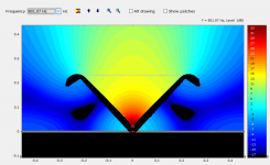
Any AxiDriver experts in the house? I modeled my wg to see if the sim matches reality. This was only done up to 10khz to save time but the result is fairly close I think considering the sim is an axisymmetric device, and I normalized to 20deg to match how the wg is eq'd. AD can't do the mids so I tweaked the motor parameters on the hf to get output down low. The pattern shown is narrower but that could just be the way VACS establishes 0dB. The main issue i see is the response below 1khz in the sim. Oviously the pattern on my 18" wide wg does not maintain control down to 300hz. I've talked to another member who said he sees the same thing in AD sims. Can anybody else verify this, or maybe I'm doing something wrong?
Attachments

If you need a volunteer to help create a (robust) installer then I would be happy to donate some time (nb am a developer by day, albeit 100% *nix these days, so might be somewhat familiar with some of the issues).
+1 3ll3dood would be good for this I think.
+1 3ll3dood would be good for this I think.
This discussion was moved to a separate thread to avoid the OT complication.
1) True, but if a 6 dB crossover was used on the BMS 4552, at 4 watts (instead of 1) you would see the same distortion as shown in post 146. The 4552 needs to be crossed high to be clean.
2) Not different, just a bit louder. The graph below shows the TC9FD in purple, a DH1A (3" diaphragm, the lowest distortion down low of all the compression drivers I have tested) and the TCFD 3.5" cone, you can see it has way less distortion.
3) Lower distortion % as direct radiator, but far less output. The cone is obviously handling the lesser pressure (lower compression ratio) of the horn way better than compression drivers. It can go another octave lower with good output and low distortion than the test shown below.
4) The large BMS drivers only have a bit more output down low than the DH1A.
I will be starting on some wider horns for the TCFD 3.5" cone later today, but don't expect to post any results until after the new year.
Art
Thank you for this response and your interesting work here. I'm going to have to see if I can do some multitone distortion testing myself.
Any AxiDriver experts in the house? I modeled my wg to see if the sim matches reality. This was only done up to 10khz to save time but the result is fairly close I think considering the sim is an axisymmetric device, and I normalized to 20deg to match how the wg is eq'd. AD can't do the mids so I tweaked the motor parameters on the hf to get output down low. The pattern shown is narrower but that could just be the way VACS establishes 0dB. The main issue i see is the response below 1khz in the sim. Oviously the pattern on my 18" wide wg does not maintain control down to 300hz. I've talked to another member who said he sees the same thing in AD sims. Can anybody else verify this, or maybe I'm doing something wrong?
Hi Nate,
I am a bit, What you see in the Sim at the lower range is the reflection on the surface behind the waveguide.
This has little effect at high frequencies because of the directivity of the waveguide, but starts to come in where the waves bend around.
What you can do is;
a - extent the model with a straight part of ca 10 meter at the throat (diameter of the compression driver output). So that the waveguide starts at 10 meter from the driver. This way the reflection is 20dB down if you render the directivity plot at a 10m distance from the waveguide apex (you must enter 20m in Axidrver because it ' thinks' from the zero-wall.
b-use ABEC, here you can also do axisymmetric and in real farfield condition. It also calculates faster than AxiDriver because it is multicore, also in the analysis part.
You have to also model the outside of the waveguide (can be a bit more rough) or the results will be invalid
greetings
Kessito
Last edited:
- Home
- Loudspeakers
- Multi-Way
- Mini-Synergy Horn Experiment