http://www.diyaudio.com/forums/vend...e-r-2r-sign-magnitude-24-bit-384-khz-299.html same mod and there is capacitors wth transistors. But we have not +-4 vdc but 3.6vdc in your mod oneclock we have drop voltage? If yes it is lower output level from raw out? or we stil have 1.4v rms raw output?
By Oneclock "The feedback at the emitter of transistor is a Sulzer Super-Regulator. Provides +4 and -4 vol. Vout Instead of +3.4 and -3.4 vol. Vout proposed by AECM circuit." see post 4101
Thank you! i dont know but i dont have seen that post! So im prepering for soldering, but stil dont know what to do whit prevesly addes 4x470uf caps to big ceramic cap, it one oneclock photos, what you think?

Can any body help me what capacitor in v2 soerkis it it? what capacitive and dialctric? I Thnink it is 47uf X5R .. i have burn it 🙂
How the heck did you burn it? Indeed it is 47uF X5R.
I have check it by multimetr on diodes 🙂 I have done BC upgrade and stil want to have prewesly solderet 470uf polimer on the top of 47uf, I must it do again and one 47 uf burn it. For now i have playing without one 47uf , but whit all 4x 470 uf and transistor upgrades🙂
dam1021-12 distortion problem with 192khz ?
Soekris
I got both rev2 dam1021-12 & dam1021-05.
After simple connection, In: optical Out:XLR , AC 2x9vac power
I heard strange sound with the 0.012%board while 0.05% board is OK.
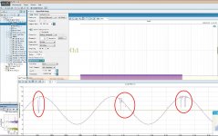
So I used the APx525 to check and found problem with the sine wave.
Do you have any suggestion ?
Jay
Soekris
I got both rev2 dam1021-12 & dam1021-05.
After simple connection, In: optical Out:XLR , AC 2x9vac power
I heard strange sound with the 0.012%board while 0.05% board is OK.
So I used the APx525 to check and found problem with the sine wave.
Do you have any suggestion ?
Jay
Attachments
Last edited:
http://www.diyaudio.com/forums/vend...e-r-2r-sign-magnitude-24-bit-384-khz-299.html same mod and there is capacitors wth transistors. But we have not +-4 vdc but 3.6vdc in your mod oneclock we have drop voltage? If yes it is lower output level from raw out? or we stil have 1.4v rms raw output?
I'm using lifepo4 batteries running around 3.3 to 3.4 VDC. They are charged to 3.4V, but return quickly to 3.3V if I turn off the charging voltage while listening to the dac.
I know this is not recommended for the voltage for this dac, but it sounds pretty good to me 🙂
I haven't measured the raw output, but I use the raw output, and it has plenty of gain for me. I did look for DC offset, and didn't see any, it was either 0 or 1mv with my meter.
Soekris
I got both rev2 dam1021-12 & dam1021-05.
After simple connection, In: optical Out:XLR , AC 2x9vac power
I heard strange sound with the 0.012%board while 0.05% board is OK.
So I used the APx525 to check and found problem with the sine wave.
Do you have any suggestion ?
Jay
First, 2x9V AC power is too high voltage, it probably don't have anything to do with your problem but could burn you board....
Questions: Is it only with 192 Khz using Optical in there is a problem ? If so then it's probably your optical transceivers, not very many work that good at 192 Khz....
First, 2x9V AC power is too high voltage, it probably don't have anything to do with your problem but could burn you board....
Questions: Is it only with 192 Khz using Optical in there is a problem ? If so then it's probably your optical transceivers, not very many work that good at 192 Khz....
Thanks Soekris,
I will do more research with the dac board and keep you update.
Hope the board is not yet burnt.
PS. trans 2x9vac is too high ? and you know, will low load the trans sec.wind voltage will increase to 2x10V~ or even a litter bit more.
For DC voltage input, +-12V is Good ?
How much would it run me in parts to build a good single-ended Soekris dac?
I've been waiting on the dac1101 but I have soldering gear coming for Christmas, so I might just build one.
I like the Amanero USB on my Audio-GD Master-11 so I'll probably use one of those unless there's a better USB input for the Soekris.
I've been waiting on the dac1101 but I have soldering gear coming for Christmas, so I might just build one.
I like the Amanero USB on my Audio-GD Master-11 so I'll probably use one of those unless there's a better USB input for the Soekris.
Thanks Soekris,
I will do more research with the dac board and keep you update.
Hope the board is not yet burnt.
PS. trans 2x9vac is too high ? and you know, will low load the trans sec.wind voltage will increase to 2x10V~ or even a litter bit more.
For DC voltage input, +-12V is Good ?
Specs are clear: 2x 7-8V AC or +- 7-15V DC, see also manual. Your board are probably fine, but with transformer AC input you need the margin for line and load variations....
Dear SOEKRIS,
I have committed sacrilege and have removed the Vrefs and have replaced them with batteries and regulators to maintain the batteries voltage. The batteries are more akin to capacitors than the typical way batteries are used.
Not asking for help with this because all seems to be fine and the board has not burned up or anything like that. And I know you have no desire to give your approval for this. It is quite involved and I doubt there are many who would want to do it anyway
My question: where is the best place on the board to tie all of my ground wires from the batteries and their regulator/"chargers"?
What would you recommend: the ground points on J1, the ground points on J2, or the ground pads for the large electrolytic caps (no longer there so the pads are available)? Which of these spots has the best connection to the ground plane on the board? J2 has the advantage of a central location as long as those points are up to the task. I am remembering your post about not using those points for voltage input and am not sure if that same counsel applies to the ground, also.
I am getting the green LED to light. Have a problem with the positive regulator that replaced the positive Vrefs that is due to something I have done and I know it can be fixed. I bring this up to say I have not connected it to the rest of my system yet. I do not know if my DAC will make music at this point but since I have to deal with the regulator problem I thought it would be a good idea to BEG for your advice on the best ground point.
Thanks and take care,
Dear SOEKRIS,
I have committed sacrilege and have removed the Vrefs and have replaced them with batteries and regulators to maintain the batteries voltage. The batteries are more akin to capacitors than the typical way batteries are used.
Not asking for help with this because all seems to be fine and the board has not burned up or anything like that. And I know you have no desire to give your approval for this. It is quite involved and I doubt there are many who would want to do it anyway
My question: where is the best place on the board to tie all of my ground wires from the batteries and their regulator/"chargers"?
What would you recommend: the ground points on J1, the ground points on J2, or the ground pads for the large electrolytic caps (no longer there so the pads are available)? Which of these spots has the best connection to the ground plane on the board? J2 has the advantage of a central location as long as those points are up to the task. I am remembering your post about not using those points for voltage input and am not sure if that same counsel applies to the ground, also.
I am getting the green LED to light. Have a problem with the positive regulator that replaced the positive Vrefs that is due to something I have done and I know it can be fixed. I bring this up to say I have not connected it to the rest of my system yet. I do not know if my DAC will make music at this point but since I have to deal with the regulator problem I thought it would be a good idea to BEG for your advice on the best ground point.
Thanks and take care,
GND should be closest to what you replaced, but due to the large GND plane and low currents it's not that critical.
So if you're using the batteries as vref, a good GND point is at the XLR connectors or J6, J7 and J8.
If you're using them for main power then GND should be at the capacitors you removed or at J1 or J2.
Dear SOEKRIS,
Thanks very much.
None of my ground wires are pointed towards the output so I will use the capacitor pads.
Now to see if it will work for me.
I think the positive side pulls more current than the negative side and I need to adjust my regulator to compensate. I am using the TI TPS7A4701 which has those solder pads for adjusting voltage.
Waited to see if you would respond to my kook question before working on the regulator voltage!
nige2000 and randytsuch have got theirs to work with this and are very pleased with the result. Nigel reports he is getting the best sound he has ever heard. I know Randy is happy but neither he nor I have listened to as many DACs as Nigel so that makes his opinion noteworthy.
We are limited to 3.3 volts with the batteries but they have not noticed any reduction in level. We could "overcharge" them but then who knows how that might affect the ESR?
AS I pontificated before: the SOEKRIS DAC will prevail!
Hi Guys, wanted to see if you can help me a bit on the power regulator
question#1: I was going to go with Classic Reference 78xx power supply linear regulator from DIYINHK. I was a bit confused on whether i need the +/-12v only or the dual +/- 12v
question#2: Should i go with the classic 78xx or the 4.17uV Ultralow noise DAC power supply regulator based off TPS7A47 (again from DIYINHK). The TPS7A47 is pretty expensive so wanted to make sure it makes sense to go for it
I a connect the dots, i think i only need the +/-12V but i wasnt sure so wanted to check.
Thanks
Hello,
Finally, we tried (Oneoclock and me) the superegulator mod. From the measure view, the results are huge (Very low impedance), but our surprise "subjetive point of view" is that we can hear this upgrade and is really big achievement (soundwise).
I our oppinion is a must, very clean highs like the mod 1, plus a deep bass full of details, much more equilibrated.
Is the best DAC that we heard until this moment
We are very happy :-D
can you tell us where exactly you have made the mod? with pics?
if i am not wrong you can go back a few pages and exactly see what they did with pictures
Last edited:
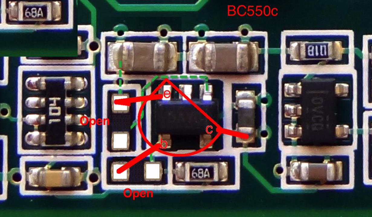
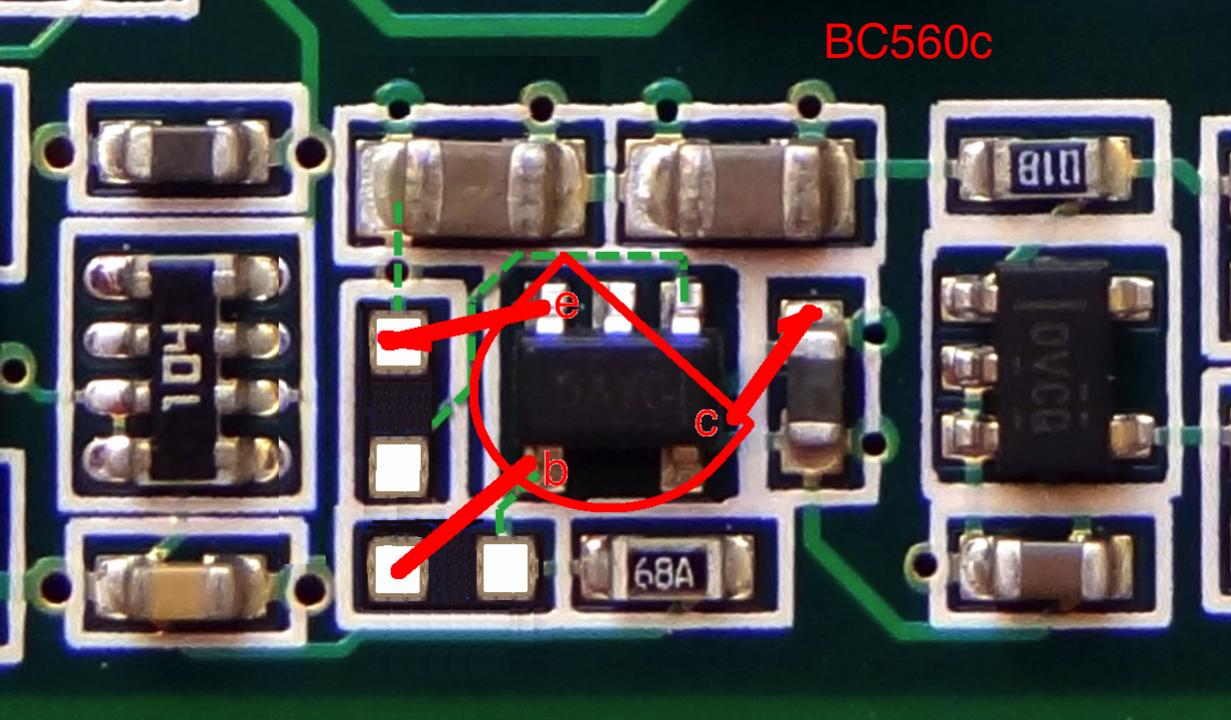
This is mod with add BC550 and BC560 , very good mod! it is couple page behing. I have BC's and 470uf polymer caps added to 47uf orginal capacivity.
I'm sorry. I modify the drawing for the Short not appear.
5v ldo regulator, is it capable for the extra bc550-560 current?
5v ldo regulator, is it capable for the extra bc550-560 current?
I haven't noticed any real increase in current draw on my test boards and I run +/-14VDC> They don't get any warmer than they already were prior.
- Home
- Vendor's Bazaar
- Reference DAC Module - Discrete R-2R Sign Magnitude 24 bit 384 KHz