My 😉 was an blatant attempt to make you move apart the magnets in your model. I have looked at an empty canvas in thas application and given up. I thought it would be an easy edit - maybe not so. I would however be interested in getting the model also to twiddle with. Maybe that could get me going. Please 🙂
//
//
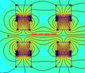
Just to be sure - I drew the conductors in the drawing as I interpret it. If this is correct I don't see how it can be considerable improved. But I fear I miss something as the parenthesis in your statement "distance from magnet to magnet (from front to back)" makes me wonder what you mean.
//
//
Attachments
Ok...i have no problem...Send him the details...Maybe a collective effort can bring better results!
Ok - distance in the horizontal plane when driver is mounted in playing mode? That would be 4mm - is that to long? Maybe soundofvoid is reaching for an 1,7mm xmax?
//
//
Ok...i have no problem...Send him the details...Maybe a collective effort can bring better results!
Is that possible over pm?
//
yes i cant send it by Pm,
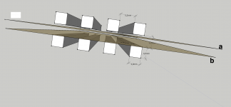
What i mean is this you draw the 4 conductors correct, but you cant see clearly there that the the last outside ones are in a much higher field then the middle 2. you could make it more even by putting the rows slightly more to each other. you will gain field strength and as far is i know a more even field.
What i mean is this you draw the 4 conductors correct, but you cant see clearly there that the the last outside ones are in a much higher field then the middle 2. you could make it more even by putting the rows slightly more to each other. you will gain field strength and as far is i know a more even field.
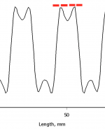
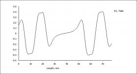
Look at the left and right peak only the rest i did ot want to do correct :0
you can see the dall between the peaks is smaller and fieldstrength is slightly higher. compared to the right one. the right the magnets are 9 mm appart the left is 7 mm appart.
well it all depends on what the netto effcieiency is of having more coil running through the lesser field strength compared to the slightly higher
Attachments
Jepp I see it. But the whidt is also smaller so you get lesser current in there. Or drive the membrane by a smaller portion if the area. F=BIL. But probably how even (distorsion?) the magnetic field is of importance. I suppose it also has to do with rigidity of the carrier (caption etc) is - and now one loses efficiency due to weight 🙂
Its a wonderful optimization maze.
//
Its a wonderful optimization maze.
//
Last edited:
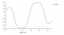
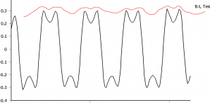
That B, is that when membrane is equal distance form the magnets (i.e. as you drew the membrane position in the femm model)?
//
//
well i am no expert on femm. but i believe th 0.4 testla point is in between the magnets, then the field gets weaker and weaker until you are in the midde of the magnet where it is essetial 0 then grows stronger the other way around..
oh and i see i misplaced one point by 0.5 mm thats the reason why it creeps up to the right a little
oh and i see i misplaced one point by 0.5 mm thats the reason why it creeps up to the right a little
another thing.
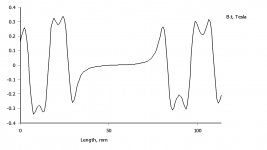
if you dont countersink the magnets in the metal. you gain a little more flux as well. because it saturates in these small parts so there is no use other then, maybe more rigid glue wise
its not much but right is just ordinair 4 mm plate without counterunking and left is with countersunked magnets in a 5mm plate
- Home
- Loudspeakers
- Planars & Exotics
- My own magnetic planar driver