I can calculate the repelling force through K&J magetics calculator.
Not now...i'm out of here for a drink!
Not now...i'm out of here for a drink!
Lets say hold strength. off course there is a gap of 4 mm in between so its many times lower then that. still its allot of force.
i have seen metal bend i had some 8mm thick x 20 mm metal bend in the 20mm direction over a spanwidth of 30 cm
magnets used where only 40x20x5 8 kg pull force, sandwiched between the 2 times 300x20x8mm. on the other side of the 1mm gap there was the same contraption, and it just bended the whole metal. you dont want your fingers in between.
ok 🙂 np al my comments are just side notes, i am in no way an expext in this , just some things i noticed 🙂 i will do some drinking of my own as well ! Cheers!
I've made some calculations.
According to the calculator the repelling force between two of the 4X4X4.5mm magnets at N50 and at 4mm apart is 3.27 Kgs.
Multiply X 4 at each row = 13.08 Kgs
Multiply X 9 rows of magnets = 117 Kgs.
That's the worst case scenario of course...
According to the calculator the repelling force between two of the 4X4X4.5mm magnets at N50 and at 4mm apart is 3.27 Kgs.
Multiply X 4 at each row = 13.08 Kgs
Multiply X 9 rows of magnets = 117 Kgs.
That's the worst case scenario of course...
I've made some calculations.
According to the calculator the repelling force between two of the 4X4X4.5mm magnets at N50 and at 4mm apart is 3.27 Kgs.
Multiply X 4 at each row = 13.08 Kgs
Multiply X 9 rows of magnets = 117 Kgs.
That's the worst case scenario of course...
I have to ask my brother to stand on it in order to shut it... 😉
//
Agree with WrineX - this must be femme:ed - otherwise really a guess... and most probably not optimized.
It would be nice to see that there is more open than closed area in the "grill" also...
//
It would be nice to see that there is more open than closed area in the "grill" also...
//
I've made some calculations.
According to the calculator the repelling force between two of the 4X4X4.5mm magnets at N50 and at 4mm apart is 3.27 Kgs.
Multiply X 4 at each row = 13.08 Kgs
Multiply X 9 rows of magnets = 117 Kgs.
That's the worst case scenario of course...
5mm plate with all those slots will never hold 117 kg im afraid. without bending. if it does bend you might have problems with the patend of BG 😉 haha they patented the fact there structure bend 🙂
Ooops mistake: At N50 and 4mm apart the force is 29.5 Kgs.
At N50 and 5mm apart it's 23.9 Kgs.
At N42 and 4mm apart it's 24.6 Kgs
At N42 and 5mm apart it's 20 Kgs.
At N35 and 4mm aprt it's 20.6 Kgs
and at N35 and 5mm apart it's 16.7 Kgs...
I think there will be no problem with steel bending...
You have to think that it's widely distributed and most of the problem is at the middle of the rows...that's why i have them connected together.
If that won't be enough i have provision for an extra cross steel bar at the middle reinforcing the metal exactly where it counts.
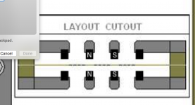
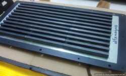
Like this right?
Yes, that's the idea more or less...
There will be a cut into the metal so that the magnets will "fit" in.
It makes positioning and gluing in place much better and stable for many years.
At the exit point of sound wave, the steel will be chamfered.
This will be much better than the run of the mill steel plates...
I don't like the perforated and bended thin steel plates of the B&G.
They are suspect of ringing for once and the muffle the sound...
To my eyes they tried to keep the cost down on the metal and left not enough openings in order to keep the structural integrity.
By the way it was not their idea at the first place.
Monsoon had done it years before.
i think they came up with the bulged idea after they noticed there steel is not capable 🙂 but it is kind of a usefull thing in the end 🙂
More updates will follow as the parts will start to arrive.
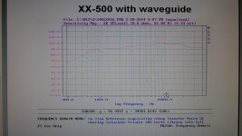
Plus an in-depth analysis of the XX-500...
From Monday...but in the mean time feast your eyes...planar galore!
Plus an in-depth analysis of the XX-500...
From Monday...but in the mean time feast your eyes...planar galore!
Attachments
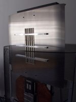
Tomorrow i will receive a photo from the first actual foil.
Let's hope it resembles my design!
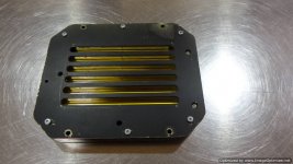
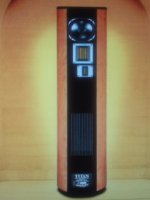
I have promised to talk about the Quadral XX-500 that has been my absolute favorite so far for a midrange driver.
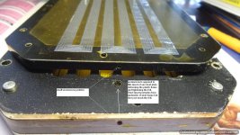
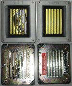
Dimensions of the frame are 13X16cm whereas the visible part of the vibrating area is 6.8X11.2cm.
The steel plates are 3mm thick of treated steel (galvanized?) that have 6 slits each.
The slit openings are 7.5mm wide and the solid steel bars are 4.5mm wide.
They support N42 neo magnets (3.5X3.5X50mm) that have been double nickel coated.
The first production run was with N40 neo magnets with a PU coating that unfortunately didn't last.
As a result the magnets deteriorated, producing fine magnetic dust and finally dislocated from the steel plate ripping off the foils.
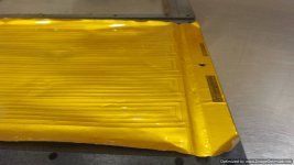
The foil is from 20 micron Kapton (later with Kadalex?)with a 20 micron aluminum trace (1mm wide) on it.
The trace runs on a 6 lanes pattern having about 50% coverage of the vibrating area (11X13 cm).
The plastic frames have a thickness of 5mm (leaving the foil a +/- 1.5mm of travel), employing a clever system of tensioning with a worm screw.
The impedance is an exact 8 Ohms having an SPL of more than 90db...
A wild guess is it can take about 80 Watts before melting!
It sounds FABULOUS! Open detailed and fast...
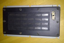
It has no back loading with cloth or any other means as it was used with a back chamber loaded with acrylic foam.
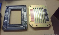
I have CNC cut a slightly deeper aluminum frame instead of the flimsy plastic one to provide a better support and to boost slightly the output.
In the process of modifying my speaker (VULKAN MKV) i have added a second mid and a second tweeter (XX-1000) to even the original somewhat bass heavy character of sound.
Then added a second smaller woofer (in acoustic suspension) to make the coupling with the 10" TL loaded main woofer even faster and easier.
Of course with external passive Xover...
Anyway the subgect is the XX-500...
Here are some photos...
Let's hope it resembles my design!
I have promised to talk about the Quadral XX-500 that has been my absolute favorite so far for a midrange driver.
Dimensions of the frame are 13X16cm whereas the visible part of the vibrating area is 6.8X11.2cm.
The steel plates are 3mm thick of treated steel (galvanized?) that have 6 slits each.
The slit openings are 7.5mm wide and the solid steel bars are 4.5mm wide.
They support N42 neo magnets (3.5X3.5X50mm) that have been double nickel coated.
The first production run was with N40 neo magnets with a PU coating that unfortunately didn't last.
As a result the magnets deteriorated, producing fine magnetic dust and finally dislocated from the steel plate ripping off the foils.
The foil is from 20 micron Kapton (later with Kadalex?)with a 20 micron aluminum trace (1mm wide) on it.
The trace runs on a 6 lanes pattern having about 50% coverage of the vibrating area (11X13 cm).
The plastic frames have a thickness of 5mm (leaving the foil a +/- 1.5mm of travel), employing a clever system of tensioning with a worm screw.
The impedance is an exact 8 Ohms having an SPL of more than 90db...
A wild guess is it can take about 80 Watts before melting!
It sounds FABULOUS! Open detailed and fast...
It has no back loading with cloth or any other means as it was used with a back chamber loaded with acrylic foam.
I have CNC cut a slightly deeper aluminum frame instead of the flimsy plastic one to provide a better support and to boost slightly the output.
In the process of modifying my speaker (VULKAN MKV) i have added a second mid and a second tweeter (XX-1000) to even the original somewhat bass heavy character of sound.
Then added a second smaller woofer (in acoustic suspension) to make the coupling with the 10" TL loaded main woofer even faster and easier.
Of course with external passive Xover...
Anyway the subgect is the XX-500...
Here are some photos...
Attachments
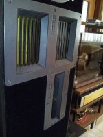

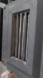
Procedure:Loosen up the clamping screws in this area only.
One worm screw is "pulling" out the plastic frame (the one that has the foil attached) as it is screwing against an inert metal insert protruding from the adjacent steel plate.
When foil looks free of wrinkles re-tighten the clamping screws...
Presto!
One worm screw is "pulling" out the plastic frame (the one that has the foil attached) as it is screwing against an inert metal insert protruding from the adjacent steel plate.
When foil looks free of wrinkles re-tighten the clamping screws...
Presto!
This was all quadral design?
- I don't like the square "horn" in front of the driver.
- Lighter membrane increases efficiency
- "Open back"? ... If its push-pull it must be a symmetric front back design (or closed).
//
- I don't like the square "horn" in front of the driver.
- Lighter membrane increases efficiency
- "Open back"? ... If its push-pull it must be a symmetric front back design (or closed).
//
Last edited:
This was all quadral design?
- I don't like the square "horn" in from of the driver.
- Lighter membrane increases efficiency
- "Open back"? ... If its push-pull it must be a symmetric front back design (or closed).
//
1)From what i know it was their own design...
Anyway i haven't seen anything similar used in any other speaker but in
their Vulkan MKV and Titan MKV...
2)It does but is not optimum when you want to go really lower...weird
resonances arise and the foil lacks in self damping.
3)It is totally symmetric...it doesn't have any cloth attached to it's back to
"load" the foil like in many similar drivers...
Attachments

Last edited:
- Home
- Loudspeakers
- Planars & Exotics
- My own magnetic planar driver