the sort of sinus you see is not the membrane but the flux. i pull a line between top plate and then bot plate. where the membrane would be in the neutral position from left to right. then the graph you see is the fieldstrength. you must read it from left to right. starting with the first magnet row, then the gap where the coil will be then a magnet row etc.
since poles are reversed every row the strength goes up in the gap lets say north, then drops down to neutral or 0 in the middle of the magnet and then strength goes up in the next gap to the south south. this might be not completely correct how i explain it. but the fact is you want the strenght there as high and even as possible, and poles switch every row🙂 if the fields is uneven then you will have more distortion. since its not moving evenly
also because you put north facing north on the stator the field is gone run between these and the next row.
Last edited:
sorry my explanation is not helpful neither is it correct 🙂
bottom line field strength is strongest in between rows of magmets, this is what you see in the spikes, either upward or the downward spike.
you want this spike as wide as possible ash high as possible and as smooth as possible. all things that wont fit together verry well as usual. wider means less strength and not smooth. to sloce mean strong field not really flat, and not wide enough to put a few traces of coil in between
Yes then I have the same understanding and my drawings are ok. In post #91 the red line represents an (exaggerated?) view of the membrane as a result of (the uneven) magnetic field and the position of the traces on the membrane moving through the 0 crossing.
("the sort of sinus you see is not the membrane but the flux." - yes but the flux drives the membrane so it will have a direct correspondence to what happen to the membrane - take or give how the traces are layed out - rigth?)
//
("the sort of sinus you see is not the membrane but the flux." - yes but the flux drives the membrane so it will have a direct correspondence to what happen to the membrane - take or give how the traces are layed out - rigth?)
//
...where the membrane would be in the neutral position from left to right. then the graph you see is the fieldstrength.
What does a graph of the fieldstrength look like if the line was drawn away form the "neutral" position? Say much closer to the magnets - e.g. near max.
Or draw a line 90 deg to see how it changes as the membrane swings between 0 and xmax (say in the middle of the peak - it now docent matter where on the peak as it is now so flat).
//
Last edited:
Y
("the sort of sinus you see is not the membrane but the flux." - yes but the flux drives the membrane so it will have a direct correspondence to what happen to the membrane - take or give how the traces are layed out - rigth?)
//
well yeah the outer coil; would be driven a little harder then the middle section i doubt you hear it but it will show up in distortion measurements. so rather have it smooth.
What does a graph of the fieldstrength look like if the line was drawn away form the "neutral" position? Say much closer to the magnets - e.g. near max.
Or draw a line 90 deg to see how it changes as the membrane swings between 0 and xmax (say in the middle of the peak - it now docent matter where on the peak as it is now so flat).
//
ideal it should be equal since its a push pull system. will take a look later this day will measure it 0.5 mm from front plate. so at 1.5 mm excursion

that is already pretty ok, could tweak it a little by increasing the gap ever so sligtl. or play with the distance between rows. so you got 2 parameter and 2 goals. to meet
good even horizontal field strength
good even vertical field strength along the excursion
but both are affected by the 2 parameters. so there should be a compromise somewhere in between.
good even horizontal field strength
good even vertical field strength along the excursion
but both are affected by the 2 parameters. so there should be a compromise somewhere in between.
After all these calculations i did some measurements to some of my opened drivers.
The XX-500 has 3.5X3.5 magnets with 8mm spacing between magnets of the same side and a 3mm spacing between the magnets of the opposite side with similar foil pattern.
The L-EMIM has 11D X 6.5W mm ceramic magnets that are 8mm spaced side by side and 4mm spaced opposite with a full coverage pattern.
The Fostex FS21 has 7D X 10W mm samarium cobalt magnets spaced at 9mm same side and 3mm opposite side again with similar to mine pattern.
So we see that there is a pattern in very successful drivers of much more spacing between same side magnets than opposite magnets.
Can you comment in these findings?
well i one thing would be sensitivity and cost? thats my bet. maybe the intended to be used with similar 87-90 db efficiency drivers ? there is no use in spending extra money if you have to tame them with a resistor.
i cant believe the 11dx6.5w and a gap of between rows of 8 mm delivers an even field. maybe they needed the extra space for conductor. so they could use heavy traces and still get a high enough impedance. so the power handling goes up. maybe they wanted to use as much coil on the membrame as possible. i know with the weak magnets this sounded the best in the high frequency department. weak magnets use allot of coil 🙂
i would suggest model all of them see whats happening. and compare.
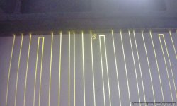
there is a reason why magnepan used smaller width magnets for the high frequency, 1 to get as much wire in a small erea or dispersion sucked, second i believe is to get a decent coverage of coil versus mylar. if you put on trace on a huge membrame and add the magnets it sound honky and high frequency wont extend that much.
i say model and try try try 🙂 or ask someone who knows how to deal with coil modeling in the magnet structure in femm
i cant believe the 11dx6.5w and a gap of between rows of 8 mm delivers an even field. maybe they needed the extra space for conductor. so they could use heavy traces and still get a high enough impedance. so the power handling goes up. maybe they wanted to use as much coil on the membrame as possible. i know with the weak magnets this sounded the best in the high frequency department. weak magnets use allot of coil 🙂
i would suggest model all of them see whats happening. and compare.
there is a reason why magnepan used smaller width magnets for the high frequency, 1 to get as much wire in a small erea or dispersion sucked, second i believe is to get a decent coverage of coil versus mylar. if you put on trace on a huge membrame and add the magnets it sound honky and high frequency wont extend that much.
i say model and try try try 🙂 or ask someone who knows how to deal with coil modeling in the magnet structure in femm
if you would make it as i suggested with a smaller row width, you could end up with a higher efficiency and lower distortion. but how the frequency response is or how high it will reach i dont know. it also depends on the weight of the foil use etc.
There's no use in any more speculating...
I understand that you win some you loose some either way you go...
I will go on as planned and will measure the drivers with different magnet strengths and gradual opposite spacing.
I 'll then see what comes out.
There are some things that i am determined to do in this driver:
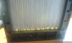
1)The magnets will be sinked 1mm in a metal "channel". I've seen too many detached magnets and ripped foils to make the same mistake.
2)It will be 8 Ohms no matter what...as it suits me with the speaker designs i have in mind.
3)I will try to get about 90db/W/m (it's enough) and a full output at 250Hz.
4)If hard pressed i will use 5X5 magnets spaced at 8mm on same side and minimum 4mm spaced opposite side.
5)The spec of magnet power (N?) will be determined after seeing what happens when you up the ante in the current design.
6)I will at least try to see if i can make a sandwich kapton foil. I have found them as thin as 15micron plain and 15 micron with pressure sensitive high temp. (silicone) adhesive (+40 micron).
The manufacturer claims that if hard pressed the adhesive layer reduces to 25 micron making a total of 15(Kapton)+20(trace)+25(adhesive)+15(Kapton) = 75 micron which looks totally acceptable for a panel that i will cross at 3.5-4KHertz...
My four foils are in the mail as we speak.
I have received the notice for the custom magnets from the post office.
Interesting times ahead!
I understand that you win some you loose some either way you go...
I will go on as planned and will measure the drivers with different magnet strengths and gradual opposite spacing.
I 'll then see what comes out.
There are some things that i am determined to do in this driver:
1)The magnets will be sinked 1mm in a metal "channel". I've seen too many detached magnets and ripped foils to make the same mistake.
2)It will be 8 Ohms no matter what...as it suits me with the speaker designs i have in mind.
3)I will try to get about 90db/W/m (it's enough) and a full output at 250Hz.
4)If hard pressed i will use 5X5 magnets spaced at 8mm on same side and minimum 4mm spaced opposite side.
5)The spec of magnet power (N?) will be determined after seeing what happens when you up the ante in the current design.
6)I will at least try to see if i can make a sandwich kapton foil. I have found them as thin as 15micron plain and 15 micron with pressure sensitive high temp. (silicone) adhesive (+40 micron).
The manufacturer claims that if hard pressed the adhesive layer reduces to 25 micron making a total of 15(Kapton)+20(trace)+25(adhesive)+15(Kapton) = 75 micron which looks totally acceptable for a panel that i will cross at 3.5-4KHertz...
My four foils are in the mail as we speak.
I have received the notice for the custom magnets from the post office.
Interesting times ahead!
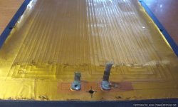
First to escape something like pictured in humid environments...where humidity is sucked in the foams surrounding the foil...slowly eating away the aluminum trace.
Second to protect it from fine metallic dust and small flying objects.
Third it enhances thermal stability as the Kapton dissipates heat evenly in it's entire body.
My friend has told me that it's something they use for pro drivers that get really abused...
Plus, anything "composite" has inherent damping abilities...as already described
in the Epsilon white paper...
Attachments
Wring, you would do me a big favor if you where to send me one of your femm files for me to start exploring this intriguing tool 🙂
//
//
Wring, you would do me a big favor if you where to send me one of your femm files for me to start exploring this intriguing tool 🙂
//
np if you can pm me an email adress
Very interesting thread, reading it from the start to this end has been like hearing thunder and waiting for the lightning flash.
Really cool thread. Looking forward to the results.
Always thought that a push-pull design (mags on both sides) is the way to go. Have done a promesing proto some years ago, and still planning to do a full size line array some day 😉
Doubt a little that you will have full response down to 250 Hz with such a relatively smallis driver though.
Thumbs up, keep going 🙂
- Home
- Loudspeakers
- Planars & Exotics
- My own magnetic planar driver