It is similar to saying that because the coil of a woofer is 10cm diameter, the actual pistonic area is not the diameter of the cone.
Hmm, is it really... in a conventional speaker driver the *whole* cone moves. Not so in a planar...
//
Well...i'm with you in this.
It's just a matter of percentage.
The actual outcome will show where the border is.
Let's hope you are wrong!
Lol!
It's just a matter of percentage.
The actual outcome will show where the border is.
Let's hope you are wrong!
Lol!
well as mentioned thats why every planar that has to go low uses high surface area. but we will see. i am looking forward to the tests!!. if it has to go bigger to get to the 200 hz point, then there is the question why not use an esl, since stacking more panels wont cost you 10000 dollars of magnets and foil. but is more complicated part wise. trannie high voltage etc. no free lunch again 🙁 damned!
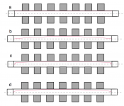
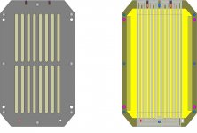
The 50% iar volume moment is probably not so far off looking at the schematic below but maybe its a bit less (but the less it is I would argue the more distorsion). An ideal transducer a) would have problem with turbulence around its edges especially if it sat in a narrow cavity which it needs to do - boundaries at high speed differences are problematic - here membrane and air. b) has not this problem as the edge is still but tensioning the membrane is a distortion generator as the spring becomes so dominant - the harder tension, the more distorsion - also dynamic unilinear. So a suspended membrane, much as a cone speaker os probably preferred and also seen in current designs e.g in the NEOs. c) seem to have only maybe 20% volume loss for a 2 sided suspension. Whats going on in a fix suspended membrane is probably something like d) with membrane tension distorsion as a consequence.
Attachments
Last edited:
I see your point.
Tensioning too much will have this "drum" effect... so a middle approach (just no obvious ripples) will be optimum.
However i am leaving more than 2cm all around of non visible foil to act as the peripheral suspension of a common woofer and i am expecting it to act a bit more homogenic in the part that counts under magnet/trace interaction.
As the foil gets progressively smaller in mid drivers, this problem (reduction of actual vibrating area) becomes more dominant.
As the driver gets larger i find it logical that the percentage of loss is declining.
Thoughts?
Your conclusions are the same as mine. Making the driven area smaller than the suspended seems to me like a good idea.
//
//
Probably it would be beneficial if the none driven peripheral was more flexible than the driven area - much like a cone speaker but with the advantage of being flat and driven over more or less the area instead of a point.
I realize that an ideal driver would stay in the position that you place it in with say your finger as it would then be in total control of the motor. How does one accomplish that?
I realize that an ideal driver would stay in the position that you place it in with say your finger as it would then be in total control of the motor. How does one accomplish that?
I still have my 1992 Martin Logan Aerius speakers (non-i). The panel and woofer cross over each other at the 500Hz.And that brings us to this driver:
I want something that can cross at eg 250hz but will not disintegrate at 100 Hz!
And my woofer will still play a fair bit at 500Hz...
Woofer loading is another topic.
Let's just say i love TL bass...
I'm told that this accounts for it's more meaty mid-range and slam over the larger airier panels which go lower in frequency.
In any case, I still like these speakers over anything which came out after them from that company.
The large CLX's I've heard were certainly more impressive, but the mega amp Krells driving them were making me long for the sound of my tubes. The scale of the sound/music was not very intimate either, rather cinematic.
My point is, I think you are spot on in theory, the devil will be in pulling off what only a few have been able to do before.
TNT:"if the none driven peripheral was more flexible than the driven area"...
It can be done...at the expense of lightness...i'm willing to try it in the future...
You make a "harder" vibrating area than the softer "suspension" sides just by gluing
another sheet of kapton to that area only...
Thus you make the central area more rigid, "forcing" the flex to the thinner sides.
Another -more expensive- way would be to place a couple more rows of magnets/traces to the sides (in the hidden area) to promote the moving of the foil as near the frame as possible...
George..."spot on in theory"... i'm happy that someone with the same experience with planar sound feels that
this is the area that makes or breaks a good speaker.
It has to sound as a system and not a sum of parts. The theory may be spot on...but you're right...i'm not expecting an easy ride on the execution...
It would be interesting to see how the conductors will be placed in the field. Also at high excursion. This is needed in order t have an opinion.
//
//
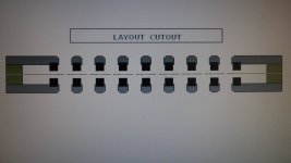
Wrinex et al...what do you think of these?
Any better now?
ah you femmed ! well i cant see very well , send me the femm ill take a look
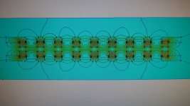
How about THIS placement of the traces?
By spreading out a bit the group of four into two pairs (2+2) i have them in the position of max field strength.
That's in exact scale for magnets 5X5. The rest is about the same...
By spreading out a bit the group of four into two pairs (2+2) i have them in the position of max field strength.
That's in exact scale for magnets 5X5. The rest is about the same...
Attachments

Last edited:
Hmmm, my idea was to try to make the traces in the lower field wider so to create more force than thinner in the higher field to get a more even force over the membrane - but as all traces are in series that don't work.
In order for that to work one ned to segment the traces into 2 or 3 branches and make these parallel. This will give you a 4 or 2 ohm driver which is not your spec.
//
In order for that to work one ned to segment the traces into 2 or 3 branches and make these parallel. This will give you a 4 or 2 ohm driver which is not your spec.
//
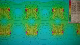
Your third magnet form the left has not the same distance as between the 2 leftmost.. it shows in the field...
//
//
I think you're being picky(-: !!!
I'll count the dots again but the general idea is there.
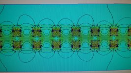
In the latest version magnets are 5X5, 4mm from opposite magnets and 8mm from the by-standing ones.
The field is stronger but there is a gap.
I thought that by spreading them in pairs each pair would be in strong field.
Plus -if you look at the big picture- the drive is much more evenly spread throughout the Kapton surface...making parasitic resonances smaller and distribution of heat better.
If there is nothing fundamentally wrong with this approach (?) it produces a much better solution...AND could be applied to the 4X4 manget version too.
I'll count the dots again but the general idea is there.
In the latest version magnets are 5X5, 4mm from opposite magnets and 8mm from the by-standing ones.
The field is stronger but there is a gap.
I thought that by spreading them in pairs each pair would be in strong field.
Plus -if you look at the big picture- the drive is much more evenly spread throughout the Kapton surface...making parasitic resonances smaller and distribution of heat better.
If there is nothing fundamentally wrong with this approach (?) it produces a much better solution...AND could be applied to the 4X4 manget version too.
- Home
- Loudspeakers
- Planars & Exotics
- My own magnetic planar driver