Forced symmetry via a tail CCS is a very good thing. If you want to swing a large I/P voltage, make the negative rail sufficiently "tall".
Transformer phase splitting at the I/P is OK, if you forego GNFB. So called Schade short loop NFB could linearize the "finals".
The cost of transformer phase splitting is substantial. Refer to Sowter's model 8920.
Transformer phase splitting at the I/P is OK, if you forego GNFB. So called Schade short loop NFB could linearize the "finals".
The cost of transformer phase splitting is substantial. Refer to Sowter's model 8920.
I've auditioned the $15 Edcor transformer, and it's good enough (it's quite surprising!). I wouldn't say it's up to Sowter or Jensen quality, but it sounds good enough.
Foregoing gNFB would be OK, depending on the quality of these EICO output trannies.
What's scaring me away from an input transformer is the question of where to put the volume control potentiometer. If you put it just before the transformer primary, it looks like it destroys the frequency response. There's probably a way to do this, but I'm not aware of it, and I'm not smart enough to figure out how it should be done.
OK, so back to the basic Grande.
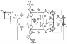
I made a sim in LTspice, and it looks really good. I chose a Hammond 1650H model that I had handy. It doesn't look like a very good OPT (very limited HF bandwidth), but it allows me to sim the circuit. I'm going to proceed on the assumption that the real-life EICO OPT will have better HF bandwidth than the virtual Hammond.
--
Foregoing gNFB would be OK, depending on the quality of these EICO output trannies.
What's scaring me away from an input transformer is the question of where to put the volume control potentiometer. If you put it just before the transformer primary, it looks like it destroys the frequency response. There's probably a way to do this, but I'm not aware of it, and I'm not smart enough to figure out how it should be done.
OK, so back to the basic Grande.
I made a sim in LTspice, and it looks really good. I chose a Hammond 1650H model that I had handy. It doesn't look like a very good OPT (very limited HF bandwidth), but it allows me to sim the circuit. I'm going to proceed on the assumption that the real-life EICO OPT will have better HF bandwidth than the virtual Hammond.
--
What's scaring me away from an input transformer is the question of where to put the volume control potentiometer. If you put it just before the transformer primary, it looks like it destroys the frequency response. There's probably a way to do this, but I'm not aware of it, and I'm not smart enough to figure out how it should be done.
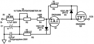
Yes, transformers do well when driven by LOW impedance circuitry. You put the volume control(s) at the I/Ps and buffer them with a voltage follower. Cascoded pairs of DN2540 depletion mode MOSFETs could do the job for you. No heater power needed for FETs and cascoding prevents reverse transfer capacitance associated HF losses.
Let's continue this "offline" via PM. I don't want to confuse Sebastian. If necessary, another thread can be started.
Wow no problem guys!
I have returned the Monitoring Audio and got back my lovely Tannoys!
But still, I can not drive them with tube power!
Eli, can you help me defining the power transformer?
As it would be custom made, we can have any voltages at the ends!
I have returned the Monitoring Audio and got back my lovely Tannoys!
But still, I can not drive them with tube power!
Eli, can you help me defining the power transformer?
As it would be custom made, we can have any voltages at the ends!
Sebastian,
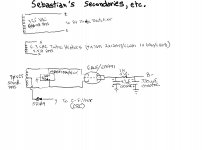
I'm uploading some "hen scratches" to be looked over.
Since the power transformer is being custom wound, the negative supplies circuitry is simplified. 😉 Notice the resemblance to the original "El Cheapo".
Either you or somebody you trust needs to review my work for error.
I'm uploading some "hen scratches" to be looked over.
Since the power transformer is being custom wound, the negative supplies circuitry is simplified. 😉 Notice the resemblance to the original "El Cheapo".
Either you or somebody you trust needs to review my work for error.
Attachments
Wow Eli, Thank you! Tomorrow, I'll change the schematic too, but I have hard times reading all you wrote, please help me! 🙂
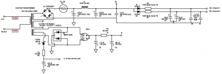
What are the diode types? I can't read that... It is MBRFxxxxxx And an SR109?
Also, do you think 600mA is enough on the 335V rail?
Anyways, it looks okay to me, but I ask for the others help too in this forum! Rongon? What do you think?
What are the diode types? I can't read that... It is MBRFxxxxxx And an SR109?
Also, do you think 600mA is enough on the 335V rail?
Anyways, it looks okay to me, but I ask for the others help too in this forum! Rongon? What do you think?
Mbrf10200ct is a full wave rectifier in a to220 package, made from Schottky diodes.
335v 600ma looks like plenty of current capacity for the proposed circuit. Full wave bridge will be necessary.
335v 600ma looks like plenty of current capacity for the proposed circuit. Full wave bridge will be necessary.
MBRF10200 data sheet.
SR109 data sheet.
Member Pete Millett provided the idea for 2 rails from a single CT winding. The "tall" rail is full wave bridge rectified. In this case, the bridge is a vacuum/SS hybrid. The "short" rail is FWCT rectified. The diode connected to the CT is insurance against several types of problems.
The "tall" rail is B- and, courtesy of the 6AL5, starts slowly. The "short" rail is C- and, being 100% SS rectified, starts "instantaneously".
Okay, quick update over here! So I went to the transformer winder, and I showed him the power transformer. He was amazed by the current on the 335V rail, but agreed to make me one!
So my order was
230V primary
Secondaries:
335VAC 600mA RMS
6.3VAC 4.5A RMS
2x35VAC 2x25mA (70VAC Center Tapped (CT) 50mA RMS)
However, he cannot make the O/P irons since he needs winding numbers, he does not design transformers... This way, the Edcor stays in plan!
For this power transformer, the winder asked for 16.000 HUF, which is equal to 57 USD according to Google!
If you want superior performance, as in dynamic headroom, you need reserves of current. 😉 Remember only approx. 1/2 the RMS current of any winding is available as DC, when cap. I/P filtration is employed.
Go back and review both my "hen scratches" and remarks. I called for a 4.7 μF. 1st cap. in the B- CRC filter. I also called for a CRC filter in the B- supply. The Nichicon KZ part is the final reservoir.
Go back and review both my "hen scratches" and remarks. I called for a 4.7 μF. 1st cap. in the B- CRC filter. I also called for a CRC filter in the B- supply. The Nichicon KZ part is the final reservoir.
Last edited:

This is a good price for a mains transformer. Do you have contact information, or do you plan to resell these ?Okay, quick update over here! So I went to the transformer winder, and I showed him the power transformer. He was amazed by the current on the 335V rail, but agreed to make me one!
So my order was
230V primary
Secondaries:
335VAC 600mA RMS
6.3VAC 4.5A RMS
2x35VAC 2x25mA (70VAC Center Tapped (CT) 50mA RMS)
However, he cannot make the O/P irons since he needs winding numbers, he does not design transformers... This way, the Edcor stays in plan!
For this power transformer, the winder asked for 16.000 HUF, which is equal to 57 USD according to Google!
Member
Joined 2009
Paid Member
Remember only approx. 1/2 the RMS current of any winding is available as DC, when cap. I/P filtration is employed.
I would add that even if well within the power rating of the transformer there are some that tend to heat up. My first amp uses a Hammond power transformer within ratings but gets awfully warm. It's designed to run that way. However, I nw prefer to over-size and run them cooler.
This is a good price for a mains transformer. Do you have contact information, or do you plan to resell these ?
Wow, nevet thought of that, maybe if the build is finished, I could do that!
Eli, is the schematic correct? 🙂
Hi guys!
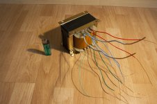
I went today to get my Power transformer!
Boy this thing is huge! I will need a strong enclosure for this one!
It weights 5.6 kg, which is equal to 12.34 lbs according to Google!
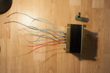
The size speaks for itself, I placed a lighter next to it.
The wires are the following:
I am so happy to have this, and now I'll start prototyping!
I need your help Rongon, Eli, to perfect this PSU stage.
If my schematic is correct, and someone corrects it, I'll take the next steps for gathering the components, and I'll document every step I make from here 😀
I went today to get my Power transformer!
Boy this thing is huge! I will need a strong enclosure for this one!
It weights 5.6 kg, which is equal to 12.34 lbs according to Google!
The size speaks for itself, I placed a lighter next to it.
The wires are the following:
- Dark greens: Neutral/Live (230VAC)
- Light green: Earth
- Light blues: Heater wires (6.3VAC)
- Blues: 70VAC CT (CT wire is lighter blue than the other 2, you can see on the picture, also at center tap, 2 wire comes out instead of one)
- Reds: 335VAC
I am so happy to have this, and now I'll start prototyping!
I need your help Rongon, Eli, to perfect this PSU stage.
If my schematic is correct, and someone corrects it, I'll take the next steps for gathering the components, and I'll document every step I make from here 😀
Attachments


In the schematic in post 174, what is the purpose of D1 and D2?
D3 in the center tap of the 70VCT winding looks like it floats the center tap below ground. But then the anodes of D4 and the reservoir and the positive ends of filter caps C8 and C9 are grounded to 0 volts. Problem? Should those be 'grounded' to the anode end of diode D3? (I've never seen this done before, and I'm not understanding exactly how it would work...)
The schematic doesn't show it, but you'll want to create a center tap out of 47R 1W resistors for the 6.3V AC winding (for the heaters). You may also want to bypass that winding to ground with two 0.01uF polypropylene film caps (to bypass RF). Maybe cheap ceramic disc caps of the same value would do just as well?
--
- Home
- Amplifiers
- Tubes / Valves
- Choosing a tube amplifier to build, HELP needed