Source?
.
Maybe we have our wires crossed but you can infer from the EVM pictures and can see from the recommended layout in the data sheet that they route power signals on the business end of the TPA both on the copper top and bottom. This breaks up an otherwise unbroken ground plane to the advantage of lower trace resistance and greater current capability where it counts.
Yeah, I had thought about paralleling PVCC as well.
What's your test rig to measure harmonics, so we maybe can compare?
What's your test rig to measure harmonics, so we maybe can compare?
It's self built. An OPA627 as a difference amplifier proceeded by some large polypropylene DC blocking caps and a resistor divider. This then feeds into the soundcard. It's part of a box I made that contains PGA mic pre amps from TI and a jig for impedance measurement too.
I had thought that my setup could be at fault but this is a balanced amp and with no load connected I get distortion as you'd expect. The measurement box is only measuring a voltage as the load is entirely separate. Only when I add the load in I get significant amounts of 2nd order distortion at low frequencies. I will be posting more measurements laterr on today, but comparisons and a discussion could prove most useful.
I had thought that my setup could be at fault but this is a balanced amp and with no load connected I get distortion as you'd expect. The measurement box is only measuring a voltage as the load is entirely separate. Only when I add the load in I get significant amounts of 2nd order distortion at low frequencies. I will be posting more measurements laterr on today, but comparisons and a discussion could prove most useful.
Reducing distortion from 0.0135 to 0.0057 is a relative improvement close to factor 3.
Absolutely this improvement is just academic.
Just my 2c😉
People saying: do good, bad happens by itself 🙂
For those who want to know:

Edit:
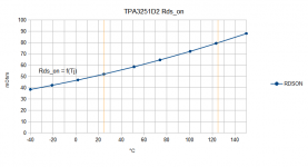
"The VGS is assumed to be 11.2V (to allow for bootstrap diode drop for the highside FETs). Metal and bondwire resistance is not included here- usually that accounts for 5-10mOhm extra."
Did some kind of an upgrade -> more to the final specs.
Changed the PVCC 2x 1000uF "Samwha" 35V for 2x 3000uF "Rubicon YXG" 35V, LC-caps changed to "WiMA MKS2" 1uF 63V (had to match them, they're 980-990nF), Phoenix connectors, EMI-Snubbers. 😀
Video anyone? 😀
https://www.youtube.com/watch?v=wBvWnpuH9go
Changed the PVCC 2x 1000uF "Samwha" 35V for 2x 3000uF "Rubicon YXG" 35V, LC-caps changed to "WiMA MKS2" 1uF 63V (had to match them, they're 980-990nF), Phoenix connectors, EMI-Snubbers. 😀
Video anyone? 😀
https://www.youtube.com/watch?v=wBvWnpuH9go
Video anyone? 😀
live at Mordlabs > cute record player
I couldn't recognize the power supply as the one you recommended earlier in the thread.
I know I know, I looked at the wrong stuff OT
Last edited:
Oh, I can't remember the recommendation.🙂 The Box shown is my portable SLA power supply with self made power meter an external input in a reused kvm switch. The PSU connected is a 15-24V notebook supply.
Plop is gone after increasing the bulk caps mentioned before (2*1000 -> 2*3000)
Plop is gone after increasing the bulk caps mentioned before (2*1000 -> 2*3000)
Anyone is getting more than ~85W cont. output power from their implementation? (34V, 1khz, both channels loaded with 3R9)
Anyone is getting more than ~85W cont. output power from their implementation? (34V, 1khz, both channels loaded with 3R9)
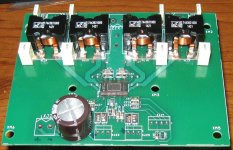
Working on it...Board stuffed except for connectors, just need to ask the machinist at work to do some machining of the heat sink.
Attachments
Last edited:
Just 1 oz...going to see what the result is...The only costs on this (besides my time) are the inductors and through hole caps.
Working on it...Board stuffed except for connectors, just need to ask the machinist at work to do some machining of the heat sink.
DUG,
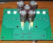
That looks real nice. A double sided implementation with fat caps on bottom? I don't know Wurth made flat wire high current inductors that look like Coilcraft. Very cool.
"Big inductor" list:
COILCRAFT RFS1412 10uH 6.2A(10%L drop) RFS1412-103ME
WURTH WE-PD SMD 10uH 10.5A(10%L drop) 7447709100
SUMIDA CDEP 10uH 11.5A(10%L drop) CDEP147NP-100MC-125
COILCRAFT SER2900 10uH 13A(10%L drop) SER2915L-103KL
COILCRAFT SER2900 10uH 18A(10%L drop) SER2915H-103KL
WURTH WE-HCF SMD 10uH 22A(10%L drop) 7443631000
COILCRAFT SER2900 10uH 28A(10%L drop) SER2918H-103KL
WURTH WE-HCF SMD 10uH 34A(10%L drop) 7443641000
You missed Coilcraft XAL8080.
And the ones from ice components.
Sorry about not furthering my design here as of yet. I've been talking with TI and trying various things out. I will post when I have something of relevance.
Doc do you happen to have any distortion measurements of your own?
Last edited:
You missed Coilcraft XAL8080.
They rate their current at 30% drop in inductance.
What would the rating be at 10% drop for a XAL8080-103MEB?
I would put it about 5.5A.
What do you think?
And the ones from ice components.
...
Could you provide a link...open to suggestions.
- Home
- Amplifiers
- Class D
- TPA3251d2