The retarding field method is grossly inaccurate when applied to real tubes.
The retarding field method is grossly inaccurate when applied by people who do not know what they do, the main source for inaccuracy is the electron cloud (space charge), i.e. not all emitted electrons end up at the anode.
If you look at the plot Ia vs Vr, it should be a straight line, but it does not, so the trick is to fit the curve as was done in the plot, at low temperatures, i.e. low heater voltage, nevertheless the error is a bit high, but not grossly high, about 10%.
As proved in my post #344 where I calculated the electric input at 604 K and the heat output at 604 K. The two values should be about equal (within 10% or so) but they are clearly very different. You need to explain that one away, Popilin.
Let’s see
So, we can use an approximate method to find out if your 604 K is realistic.
At 5 V filament energisation, from the grey body radiation loss formula,
P = k (Tf^4 - Ta^4) = 10 W = k (1050^4 - 700^4) hence k, a constant comprising the product of area, emissivity, & Stefan Boltzmann constant, is equal to 1.035x10^-11 W.K^-4.
Then
k = Area . Emissivity . Stefan-Boltzmann constant = 1.035x10⁻¹¹ W ºK⁻⁴
Regardless of cathode area!!!

Cathode area can vary an order of magnitude; sometimes more...that’s why your calculation is like throwing dice…
Ah, now I understand, your "constant" is like your planar diode which grows up or shrinks according to your need; that is!
Very accurate and realistic…

Something like 850 K by the above quick cube law estimate:
300K + (1050K - 300K) x (2/5)^1/3 = 850 K
<snip>
This is the sort of sanity check that good engineers and physicists do all the time.
For BaO-SrO
e φ = 1 eV ,….., Ao = 1 A/(cm² ºK²)
Then, at T=850 ºK
Jo ≈ 850 mA/cm²
Or
Io ≈ 3.4 A
Sanity check…
Your approach is the approach of someone who copies from books but has no actual understanding or experience. Or you are trying to impress rather than inform.
No, I am just a TV repairman, unlike you I do not have anything to prove. 😎
Like yourself, for instance.The retarding field method is grossly inaccurate when applied by people who do not know what they do
Yes, under a retarding field, most electrons return to the cathode. Virtually all, in fact, especially when the field is strong. The theory basically takes that into account - relies on it in fact. The heart of the theory is that electrons are emitted with a statistical variation in velocity (in the three dimensional sense), with a mean that is a function of cathode temperature, so how many get forced back is a function of their inertial distribution and the retarding electric field strength.the main source for inaccuracy is the electron cloud (space charge), i.e. not all emitted electrons end up at the anode.
Accuracy is also affected by mica leakage, especially in old tubes, as the currents involved in retarding field conditions are very tiny. There are other factors as well. Perusing the papers on using a retarding field method by tube factory physicists like Steven Ikehara will quickly dissillusion you that you can make practical use of it.
I note you still haven't explained how you actually did your measurements. How? What with? I shouldn't think you have an NEC harmonic type retarding field test set sitting around waiting in case I post. They are quite complex and were only made in very limitted numbers.
k = Area . Emissivity . Stefan-Boltzmann constant = 1.035x10⁻¹¹ W ºK⁻⁴
Regardless of cathode area!!!
Essentially, using normal filament voltage conditions, it is a calculation of k for that particular tube. Then we can use k to calculate for any temperature of interest. Cathode area for any particular tube is fixed. It cannot change just because you under run the filament. Emissivity does change with temperature, but for a rectifier with a relatively thick and corse oxide coating, it can be considered constant for the purpose here.
It's not throwing dice at all. Cathodes vary from tube to tube, but we are only considering one tube type here. In fact, only one example of one tube type. So cathode area is fixed. We don't need to know what it or the emissivity actually is, we only need k.Cathode area can vary an order of magnitude; sometimes more...that’s why your calculation is like throwing dice…
Pretty poor sanity check then. You've erred (presumably on cathode area) and considerably over estimated Io. Whatever the Io value at 850 K is, it has to be much less than at the normal temperature of 1050 K.For BaO-SrO
e φ = 1 eV ,….., Ao = 1 A/(cm² ºK²)
Then, at T=850 ºK
Jo ≈ 850 mA/cm²
Or
Io ≈ 3.4 A
Sanity check…
You said the temperature is 604 K - a ridiculously low value. I've posted two ways of checking it:-
a) comparing electric input with heat output (My post #344). You need to explain away that one - I note you have not attempted that;
b) Your 604 K value implies a linear dependence of temperature upon filament voltage. Its actually approximately dependent on the cube root of the voltage (My post #357). You need to explain away that one too - I note you have not attempted that either.
So why are you trying to prove things, then? You seem to be going to an awfull lot of trouble for someone who has nothing to prove.No, I am just a TV repairman, unlike you I do not have anything to prove. 😎
Last edited:
Hey Keit, the nonsense-meter is overloaded...give me a breath. 😀
Take as many breaths as you need, lady. Have a good hard think before posting. Maybe then you could handle the simple calcs I've given you.
I note you still haven't explained how you actually did your measurements. How? What with?
I already described the whole experiment, seems that you read only which concern to your own nonsense.
my result
e φ = (0.9 ± 0.2) eV
Not too bad for a couple of multimeters, a picoammeter, and two PSUs. 😎
i) Determination of cathode work function
From Richardson-Dushman equation
Jo = Ao T² exp ( - e φ / k T )
You can obtain e φ from the slope of the straight line
Ln ( Jo / T² ) = - ( e φ / k ) (1 / T) + Ln ( Ao )
ii) Determination of cathode temperature
Applying a retarding potential, Vr
Jr = Ao T² exp [ - e ( φ + Vr ) / ( k T )] = Jo exp ( - e Vr / k T )
Then you can obtain cathode temperature, T, from the slope of the straight line
Ln ( Jr ) = - ( e / k T ) Vr + Ln ( Jo )
iii) Determination of Jo
Applying an accelerating potential, Va, for a high value enough, current density reaches its saturation value, Js
Js = Jo exp [(α √ Va ) / ( k T )]
Then, you can obtain Jo from the straight line
Ln ( Js ) = [ α / ( k T )] √ Va + Ln ( Jo )
Pretty poor sanity check then. You've erred (presumably on cathode area) and considerably over estimated Io.
Total and absolutely unbelievable!!!
T=850 ºK was YOUR calculation, not mine, and it is quoted at this same page!!!
You twist my arguments shamelessly as a cheater lawyer.
And you talk about lack of honesty… 🙄
It's not throwing dice at all.
You must solve a nonlinear system of two equations and five unknowns, using a particular case and a guess, you still have three unknowns, several guesses more and you have a result, even more, you claim shamelessly that the result is accurate…I call this throwing dice. 😀
You said the temperature is 604 K - a ridiculously low value.
Definitely no, the temperature value is totally consistent, even when you do not understand
From the last plot
Ln(io) ≈ 8.77 µA
Then
io ≈ 6.44 mA
For BaO-SrO
e φ = 1 eV ,….., Ao = 1 A/(cm² ºK²)
Then, at measured cathode temperature
T = (604 ± 25) ºK
Jo ≈ 1.65 mA/cm²
Measured cathode area
Ak = (4 ± 0.4) cm²
Then, finally
io ≈ 6.6 mA
Very close, right? 😎
What is debatable is the method to measure cathode temperature, and I must agree with you that retarding potentials is not the best method, nevertheless, your “calculation” method has proven to be worse.
I got a temperature of approx 780 K for 2 V energisation.
Jo ≈ 210 mA/cm²
io ≈ 840 mA
Something like 850 K by the above quick cube law estimate:
300K + (1050K - 300K) x (2/5)^1/3 = 850 K
Jo ≈ 850 mA/cm²
io ≈ 3.4 A
So why are you trying to prove things, then? You seem to be going to an awfull lot of trouble for someone who has nothing to prove.
For the good of the readers, diyAudio is a place to learn, as you are a talking nonsense machine, somebody must stop you.
And of course, physics is funny. 😀
Hey Keit, I solved the puzzle, was easy. 😛😀
If anyone wants to know, send me a private message. Otherwise, I post the answer here. It's quite simple. 😛😀
If anyone wants to know, send me a private message. Otherwise, I post the answer here. It's quite simple. 😛😀
Last edited:
The best place is to post it here Popilin .
Hey Keit, I solved the puzzle, was easy. 😛😀
If anyone wants to know, send me a private message. Otherwise, I post the answer here. It's quite simple. 😛😀
The best place is to post it here Popilin .
No problem, only was a joke 😛
I already have the answer, but Keit is absent.
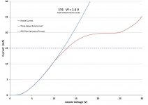
We see that the plot corresponds to the three-halves power rule up to about 10V. From 10V to about 14V, the plot veers to the right of the three-halves line. Can you say why, Popilin? I can, but I bet you cannot. If anyone wants to know, send me a private message. Otherwise, I post the answer here in a few days. It's quite simple.
Popilin, can you explain why the plot diverges away from the langmuir law between about 10 V and 12 V? I bet you can't - it's quite simple but it requires a real understanding of tubes and their construction.
I can. If anyone wants to know, send me a PM. Otherwise I will post the reason in a few days.
Last edited:
That's right. In previous posts you maintained that it is sufficient to just consider the anode voltage. I'm glad you now recognise anode voltage does not drive schottky effect, and you now think it is the electric field strength.
You twist my arguments like a cheater lawyer... again. 🙄
Almost from the beginning, introducing Schottky effect, on post#71 I said
A more accurate expression for Richardson-Dushman equation with an external electric field E can be obtained replacing the work potential φ with the effective work potential
φeff = φ – φSch = φ – √[e E / (4 π ε0)]
Then
J = Jo exp{e √[e E / (4 π ε0)] / k T}
The applied electric field increases thermionic emission lowering the potential barrier, this is the Schottky effect.
Even so, you do not understand Schottky effect.
Silly question: How do you measure the external electric field E?
Silly question: How do you do to have an external electric field E, without any applied anode voltage, Va?
So far you did not answer any of them…your rhetoric arguments are very good, but your physics is pathetic.
As I said before, in metals (conductors) according with the free electron model, the work function barrier is produced by an excess of electrons spilling out from inside the cathode to a distance of the order of interatomic distance, and these electrons cannot escape easily due to the force exerted by nuclei
Giving you the benefit of the doubt and making allowances for presumably poor english, that (local positively charged nuclei that have lost an electron) may be the case for insulators and oxide coatings, but it cannot apply to pure metal cathodes. The charge will be virtually immediately replaced from the electron gas that makes metals conductors.
You do not completely understand how metals (conductors) work.
In a metallic crystal lattice, the outer electrons (valence electrons) orbits overlap and they are shared by all the atoms in the solid; these electrons are not bound and are free to conduct current.
Typically the free electron density in a metal is 10²³ atoms/cm³ (About one electron per atom), and they form a gas, then you can think the metal is formed by ions and the electron gas.
From a classical point of view, ions exert a force over electrons in the gas, even when you did not understand it; a detailed mathematical description was given here
http://www.diyaudio.com/forums/tubes-valves/276917-why-gold-grids-28.html#post4422476
From a quantum point of view, electrons of the free electron gas are confined by a potential barrier, i.e. the work function of the metal.
I gave to you the classical explanation because you did not understand the concept of potential barrier
You don't seemn to understand the concept of work function. You talked in several posts about a "barrier potential". It isn't a potential, it's an energy. It is measured and quoted in joules or electron-volts - both units of energy.
Energy barrier and potential barrier are the same thing, and in the worst case they are equivalent concepts, because the later can be referred to potential energy barrier, even when you treat with work functions, i.e. W = e φ, some people take only φ as the work function (in Volts), particle physicists speak about mass in eV, and it is understood.
Electrons of the metal (conductor) can escape surpassing the barrier, then and only then, they can be considered part of the electron cloud (space charge); and no, Schottky effect it is not too late for them, because the barrier was already lowered by the external electric field before they were emitted, which is the essence of Schottky effect, which obviously you cannot understand.
That makes no sense at all. If they have joined the space charge, they have escaped. The horse has bolted. Whether the barrier is raised or lowered no longer matters.
As I said before, that’s the proof of your non-understanding of Schottky effect.
Well, Schottky is said to have first reported what is now known as schottky effect in his 1914 paper right enough. I can't read German fluently (esp pre-war German), and Schottky had a reputation of writing things that hardly anyone in the field could understand. When he worked for Seimens & Halske, they provided him with a few bright young Ph.D's to "translate" his works into something regular boffins could understand.
The merit of oxide cathodes was discovered and reported by Wehnelt in 1903. Much research was triggered off. Commercial exploitation had to wait until sufficiently good vacuum pumping techniques were developed, as oxide cathodes are ruined by oxygen and trace amounts of water vapour. Westen Electric were making oxide cathode types in quantity in time for WW1 and for the early carrier telephone systems of Bell. Comsumer exploitation was delayed by the higher cost. The bright emitter tungsten cathodes used in radio sets up to the 1920's were soft (ie they were intentionally gassy). Ionisation of the gas and transformer coupling increased the stage gain, allowing small filaments and offsetting the lack of emission efficiency of oxide cathodes.
It is inconceivable that Schottky, paid by Seimens to be ahead of the pack, was not aware of oxide cathodes and had not done lab work with them.
No, even historically you are wrong, because Walter Schottky did his research at the Berlin University in 1913, at least two years before he worked at Siemens & Halske.
BTW, the work of Schotky at that time was about METALS
Schottky, W., Über den Einfluss von Strukturwirkungen, besonders der Thomsonschen Bildkraft, auf die Elektronenemission der Metalle. Physikalische Zeitschrift, 1914, 15, 872-878
Something like
Schottky, W., About the influence of structural effects, particularly Thomson's image force on the electron emission of metals. Physikalische Zeitschrift, 1914, 15, 872-878
End of story.
Prosit und auf wiedersehen!

Last edited:
Popilin, can you explain why the plot diverges away from the langmuir law between about 10 V and 12 V? I bet you can't - it's quite simple but it requires a real understanding of tubes and their construction.
The question should be where is the transition point between the space charge limited region (Child-Langmuir law), and the emission limited region (Richardson-Dushman equation).
The transition point can be determined mathematically as follows
Child-Langmuir law
J = (4 εo / 9) √ (2e / m) (1 / d²) V^(3/2)
Details here
http://www.diyaudio.com/forums/tubes-valves/264781-getter-heater-b-sequencing-12.html#post4128561
Richardson-Dusman equation
Jo = Ao T² exp ( - e φ / k T )
Equating
Vt = [(9 d² / 4 εo) √ (m / 2 e) Jo]^(2/3)
For the 5R4GY at 2 V heater voltage
Jo ≈ 6.44 mA/cm²
And
d ≈ 1 mm
Then
Vt ≈ 9 V
Indeed the 5R4GY at 2 V heater voltage has a transition point at about 7 V on the Ia vs Va plot and the calculated value is about 9 V, which is remarkable, and confirms that the 5R4GY is a good approximation to a planar diode.
Let’s see your plots
As you tied the control grid and screen grid to anode, the effective distance cathode-anode was greatly reduced; at low anode voltages everything is close to normal, at about 10 V the electron cloud (space charge) is moved toward the grid plane reducing the electric field E, as a result you have a “lazy diode” until about 18 V to 20 V, beyond there, the electron cloud is depleted and saturation is reached.
In a nutshell
J = ρ(x) v(x)
A reduction of the velocity of electrons produces a reduction of the current.
My Goodness! Total and absolutely unbelievable! You still do not understand!!!
Your understanding of physics is reduced to mere…arithmetic.
If you need x in an exponential function f(x)=exp(x) you need a logarithm with base e, i.e. f⁻¹(x)=Ln(x), not 10, i.e. f⁻¹(x)=Log(x); this is elementary, even in high school.
If you want to work with base 10, e.g. instead a calculator you only have logarithm tables, you must use the following relations
Ln(x) = Log(x) / Log(e)
Log(x) = Ln(x) / Ln(10)
As you used the wrong logarithm, you did not see Schottky effect, as the Ia vs Va plot at saturation looks almost a horizontal line, with the wrong function, i.e. Log(Ia) it looks more horizontal than before.
As a final comment, your experiment was poorly designed, with heaters at full power, you can measure almost nothing.
The software does not show the points, next time you could try this
http://www.sigmaplot.com/products/tablecurve2d/tablecurve2d.php
Attachments
Anyone else like to lock these two in a room and chuck in a couple of pairs of boxing-gloves.....??
I think then it would be (At Least) more entertaining than this constant quoting and squabbling over abstruse terms and equations that few except Nuclear Physicists understand...
I have already decided on which is Sheldon and which is Wallowitz in my mind, Wonder if you have too!!.
I think then it would be (At Least) more entertaining than this constant quoting and squabbling over abstruse terms and equations that few except Nuclear Physicists understand...
I have already decided on which is Sheldon and which is Wallowitz in my mind, Wonder if you have too!!.
I have already decided on which is Sheldon and which is Wallowitz in my mind, Wonder if you have too!!.
What do you mean? I cannot understand sarcasm. 😛😀
At 5 V filament energisation, from the grey body radiation loss formula,
P = k (Tf^4 - Ta^4) = 10 W = k (1050^4 - 700^4) hence k, a constant comprising the product of area, emissivity, & Stefan Boltzmann constant, is equal to 1.035x10^-11 W.K^-4.
At 2 V filament energisation, taking your 604 K temperature as correct, since resistance is approx proportional to temperature, power is approx P = V^2 x 2/5 x 1050/604 = 2.78 W.
That is for an imaginary 5R4GY, for my real sample, measured power was
P = (2.17 ± 0.01) W
Throwing dice, … , err, with your own equation
T ≈ 683 ºK
But you forget an implicit assumption, it is supposed that temperature is uniform over the entire cathode surface, and this is wrong.
Each filament is connected to about 0.5 mm diameter wires (supposedly nickel), at its middle, it pass over a mica insulator, which in turns is fixed by two insulators (supposedly steatite) to about 1 mm diameter (supposedly nickel) anode rods, even more, anodes are connected each other by a metal plate, parallel to the mica, at about 2 mm from it.
In a nutshell, you have at least two cathode segments at different non-uniform temperatures.
Cathode temperature is anything but uniform.
Yes, under a retarding field, most electrons return to the cathode. Virtually all, in fact,…
That’s an indicator of your understanding of the experiment, if it were so, the method would be useless...without electrons you have no current…
Last edited:
Actually it's not that hard to follow, a bit like a train journey looking out of the window missing the detail perhaps. Only Popilin actually posts interpretive physics as I see it - the rest is mostly fluff IMO. I've never understood the crux of Keit's argument......surely the Schottky effect is undeniable.......?I think then it would be (At Least) more entertaining than this constant quoting and squabbling over abstruse terms and equations that few except Nuclear Physicists understand.....
Actually it's not that hard to follow, a bit like a train journey looking out of the window missing the detail perhaps. Only Popilin actually posts interpretive physics as I see it - the rest is mostly fluff IMO. I've never understood the crux of Keit's argument......surely the Schottky effect is undeniable.......?
Thanks for your kind words.
And yes, Schottky effect is undeniable, especially in metals, because it was first discovered in them.
BTW, the work of Schotky at that time was about METALS
Schottky, W., Über den Einfluss von Strukturwirkungen, besonders der Thomsonschen Bildkraft, auf die Elektronenemission der Metalle. Physikalische Zeitschrift, 1914, 15, 872-878
Something like
Schottky, W., About the influence of structural effects, particularly Thomson's image force on the electron emission of metals. Physikalische Zeitschrift, 1914, 15, 872-878
Erratum
Needless to say that my new eyeglasses does not work, seeing carefully it results to be another mica... 😛😀
BTW, anodes have separate connection, as it should be...
...anodes are connected each other by a metal plate, parallel to the mica, at about 2 mm from it.
Last edited:
I already described the whole experiment, seems that you read only which concern to your own nonsense.
"Not too bad for a couple of multimeters, a picoammeter, and two PSUs."
Oh, right. We are supposed to know that something you said in post #105 applies over 200 posts later, to post #339.
You are not trying to convey information, you are just being a smart aleck.
In any case, with a PSU, two multimeters, and a picoammeter, you could only have done a static retarding field text, which is the most hopelessly inaccurate of all the various tests derived from retarding field theory.
On the contary, it is you who are shamelessly trying to mislead people.Total and absolutely unbelievable!!!
T=850 ºK was YOUR calculation, not mine, and it is quoted at this same page!!!
You twist my arguments shamelessly as a cheater lawyer.
T = 850 K (incidentally, temperature in Kelvin is properly given as nnn K, not nnn ºK - see IUPAC) is indeed my approximate calculation based on taking filament temperature as proprtional to the cube root pof voltage.
But you took that value and "calculated" a saturation current of 3.4 A! Clearly, regardless of the validity of 850 K, it is your calculation of the consequent saturation current that is incorrect - ridiculously high!
On the way, you obtained Jo = 850 mA/cm^2 for 850 K, notwithstanding that RCA achieved only about 250 mA/cm^2 at the much higher temperature 1050 K.
It is not possible to state what your error was, because you provided no working, but you clearly made an error.
Well, you are the person who cited a reference as a source of a graph, and it turned out you hadn't even consulted that reference.And you talk about lack of honesty… 🙄
What rubbish you write!You must solve a nonlinear system of two equations and five unknowns, using a particular case and a guess, you still have three unknowns, several guesses more and you have a result, even more, you claim shamelessly that the result is accurate…I call this throwing dice. 😀
From the 5R4GY datasheet we can infer that the sturation current is around 1.5 A, 2 A max. That's one "known". We can take a work function value known to be valid for RCA tube designs (you can use your value of 1 eV if you like). That's a second known. Boltzmann's Constant is a given. We know the standard operating temperature for oxide coated filaments and cathodes (1050 K). That's a third known. For this we can use the Richardson-Dushman equation to find the current (unknown) for any other temperature (a forth unkown.)
Theres' only one unkown, and one equation needed. I explaine this earlier, here I'll explain it a diffrent way, perhaps you's read it and understand. It's only 1st year high school algebra:-
Richarson-Dushman equation:-
Isat = A Ao T^2 e^(-W/(kB T)]
Where Isat is the saturation current, A;
A is the emission surface area, m^2
A0 is the Richardson constant for the emission surface material, A.m^-2.K^-2 ;
T is the emssion surface temperature, K;
W is the surface work function, J;
kB is Boltzmann's Constant, 1.381x10^-23 J/K
As, for any given tube, A & Ao is fixed, we can define a ratio of the saturation current at two temperatures, T1 & T2:-
I1/I2 = A Ao T1^2 e^[-W/(kB T1)] / A Ao T2^2 e^[-W/(kB T2)]
The A and Ao terms are on both sides of the division and cancel out.
Combining terms we have:-
I1/I2 = [T1/T2]^2 x e^[W/(kB T2) - W/(kB T1)]
Simplifying, we have :-
I1/I2 = [T1/T2]^2 x e^[{W/kB} {(T1 - T2)/(T1 . T2)}] ........(eqn 1)
or
I2 = I1 x [T2/T1]^2 x e^[{W/kB} {(T2 - T1)/(T1 . T2)}] ........(eqn 1a)
We have one equation (eqn 1a) that take takes what we know, conditions and saturation current at one temperature, and gives us the sat current at another temperature. We don't need to know the emission area or the Richardson constant for the emission surface.
Starting with your Isat value of 3.4 A at 850 K, and your work function value, 1 eV ie 1.602 x 10^-19 J , we can calculate what the saturation current would be at normal operating temperature, 1050 K:-
I2 = 3.4 x [1050/850]^2 x e^[1.6x10^-19/1.38x10^-23 {(1050-850)/(1050x850)}]
I2 = 3.4 x 1.53 x 13.4 = 70 A.
I sincerely hope you realise that a 5R4GY will definitely NOT pass 70 amps, which it must do if your calculation of 3.4 A at 850 K is correct! The octal socket will be destroyed in seconds! The leads inside the tube will melt immediately.
Definitely no, the temperature value {604 K} is totally consistent, even when you do not understand
On the contary, itv is you who do not understand.
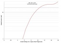
I explained why you are wrong before, with nothing but 1st year high school algebra (my post #357). Since you have a lot of trouble doing simple algrebraic calculations, here it is in graphical form:-

You can see that if 2 V filament energisation results in 604 K temperature as you claimed, the best fit line is very close to linear. That is simply impossible, because of the Stefan-Bolzmann law - radiation heat rses to the 4th power of temperature. Therefore, since the resistance rises with temperature so power is approx linear with voltage, temperature is proportional to the 4th root of power, and the cube root of voltage.
Notice that my approximation based on T proportional to cube root of V is much closer to the truth. The best fit curve pasing through 850 K and ambient (300 K) and 1050 K is quite realistic.
Notice that the dotted line from 4V to 6V lines up prceisely with the curve passing through my estimate of 780 K calculated with the more precise method I explained in my post #332.
This dotted line was copied from the chart on the 2nd page of Haller C E, Tube Filament and Heater Characteristics, Electronics July 1944. This chart is shown in some tube application manuals. It doesn't show the line below 4V or above 6 V because of course you shouldn't operate tubes other than close to 5V.
Haller uses a different mathematical approach to obtain the formula to me, but comes up with the same answer. So if you want to keep claiming I'm wrong, you better explain why Haller is wrong too.
Note that filaments in tubes designed by RCA can be tungsten, tungsten-molybdenum alloy, or nickel. My graph is completely applicable to tungsten and tungsten-moly. But for low voltgaes it will be a little bit out for nickel due to the Worthing exponent of nickel increasing suddenly below the curie point. At 2 V and above it will be fine.
The static method is hopeless. S Ikehara of NEC claims in his 1954 paper that his harmonic method is quite accurate. It does eliminate certain errors such as those due to mica leakage. It requires a heck of a lot more than a PSU and three meters though.What is debatable is the method to measure cathode temperature, and I must agree with you that retarding potentials is not the best method
For the good of the readers, diyAudio is a place to learn, as you are a talking nonsense machine, somebody must stop you.
You have no idea what you are talking about. You have no idea how tubes work - proven by the multiple errors of reasoning and calculation you've made.
Don't you think you are the one who should stop?
Originally Posted by TrippleM
The best place is to post it here Popilin .
We can take it from the above that Popilin:-
a) Is well aware I asked the question to test her;
b) Doesn't know what the answer is, despite claiming to know about tube physics.
Oh, right. You cannot answer the question, so you posted your own different question and answered that.
Perhaps if someone what sort of climate you locality has, you tell them the day's temperature.
I asked what is happening at 10V, not what is happening at 14V.
None of that has any relavence whatsoever to what's happening between 10 V and around 12V to 13 V or so. The real transition to thermallly limmitted current as per clasic textbook plots occurs around 15 V.
The reason why the measured current veers away to the right of the langmuir V^3/2 line is due to the construction of the 1T4. The filament strand is 22 mm long. The anode and grids cover most of it, 18 mm. However, while most of the filament heat is lost be radiation to the anode and grids, some is lost by conduction to the filament support structure. This causes the temperature to be low at the ends.
The plot below is from a computer model of the 1T4. Notice that the temperature is pretty even in the middle 60% or so of the filament (13 mm) but it drops away rapidly at the ends. This is a compromise RCA made inorder to fit the tube structure within a miniature 7-pin glass envelope. They did implement some thermal isolation measures not used in octal tubes, which is why the ends run at 500K and 680 K.
View attachment 501285
This temperature profile means that the saturation current at the ends is low compared to the middle. As anode voltage is increased from zero, the current follows a V^3/2 law until the ends saturate. The ends become thermally limitted at 10 V, well before the centre does so. As the voltage is further increased, saturation conditions progressively move twards the centre. That is the main reason.
The 1T4 is an RF pentode. As such it has a variable pitch control grid. In the coarse pitch parts of the grid (at each end) , the screen grid field partly penetrates between control grid turns. This means that the tube acts acts as a diode whose electric field is weaker at the ends and stronger in the middle. This partly compensates for the filament temperature profile by delaying end saturation. But there comes a point (around 10V) where the temperature profile wins out - at the ends there is no more current to be had.
Filament temperature profile effect will occur in the 5R4GY as well, without any compensation from a variable pitch grid. So the veering away from the V^3/2 curve will not be a sharp inflexion like it is with the 1T4 strapped as a diode. But it will occur.
Further, since at low temperatures a radiation heat loss falls much much faster than conduction heat flow, the temperature profile changes from an inverted bathtube shape to an arc. So the movement away from the classic V^3/2 space charge limmitted curve is greater the lower the filament voltage is.
That is the opposite of what your set of plots show. One reason why I supect your "measurements" are dodgy or faked.
Writers of textbooks for teaching like to show nice neat plots that match the theory presented, which is always simplified. Real tubes work differently - a point you don't appreciate, Popilin.
The field due to the space charge is superimposed on the field established by the "anode" (anode plus grids). As the "anode" field gets stronger, it pulls the space charge way from the filament right enough, but that just means the space charge field is more spread out.
If you were correct, increasing the anode voltage from zero would at first cause the anode current to diverge from the V^3/2 line at first, and then re-join it. That is not what happens.
Why you thought I used base-10 logarithms is a mystery to me. But it doesn't matter whether you plot a graph with base1- logs or base-e logs, the progression up the axis is the same. That's because
Log(x) = Ln(x) x 0.4343.
( 0.4343 being Log(e) )
You seem to have a difficulty understanding graph scaling.
You didn't reveal until later that you "measured" at low currents, if indeed you did in fact measure. Rather convenient for you that you kept it quiet.
I'll stay with Microsoft Excel thanks. It can do just about anything.
And when Excel is not the best tool for the job, I use Mathcad. Excel is ideal for the sort of plots in this thread. The loading of measurements was loaded into an Excel file by the instrument control software.
Excel will show you the points if you enable points (called "markers" by Microsoft) and has very flexible options. I didn't enable them in the 1T4 plots because:-
a) Unlike a plot done manually with basic instruments, the plot was done automatically with computer controlled power supplies and metering to 4-1/2 digit accuracy, as I explained. Excel's curve fitting was turned on. So each point is precisely dead on the curve - no visible random error.
b) There's just too many points. Measurements were made at 0.5V intervals, 60 points in total - They would merge together.
The best place is to post it here Popilin .
No problem, only was a joke 😛
I already have the answer, but Keit is absent.
Originally Posted by Keit
Popilin, can you explain why the plot diverges away from the langmuir law between about 10 V and 12 V? I bet you can't - it's quite simple but it requires a real understanding of tubes and their construction.
I can. If anyone wants to know, send me a PM. Otherwise I will post the reason in a few days.
We can take it from the above that Popilin:-
a) Is well aware I asked the question to test her;
b) Doesn't know what the answer is, despite claiming to know about tube physics.
The question should be where is the transition point between the space charge limited region (Child-Langmuir law), and the emission limited region (Richardson-Dushman equation).
Oh, right. You cannot answer the question, so you posted your own different question and answered that.
Perhaps if someone what sort of climate you locality has, you tell them the day's temperature.
I asked what is happening at 10V, not what is happening at 14V.
The transition point can be determined mathematically as follows
Child-Langmuir law
{....more formulae...}
None of that has any relavence whatsoever to what's happening between 10 V and around 12V to 13 V or so. The real transition to thermallly limmitted current as per clasic textbook plots occurs around 15 V.
The reason why the measured current veers away to the right of the langmuir V^3/2 line is due to the construction of the 1T4. The filament strand is 22 mm long. The anode and grids cover most of it, 18 mm. However, while most of the filament heat is lost be radiation to the anode and grids, some is lost by conduction to the filament support structure. This causes the temperature to be low at the ends.
The plot below is from a computer model of the 1T4. Notice that the temperature is pretty even in the middle 60% or so of the filament (13 mm) but it drops away rapidly at the ends. This is a compromise RCA made inorder to fit the tube structure within a miniature 7-pin glass envelope. They did implement some thermal isolation measures not used in octal tubes, which is why the ends run at 500K and 680 K.
View attachment 501285
This temperature profile means that the saturation current at the ends is low compared to the middle. As anode voltage is increased from zero, the current follows a V^3/2 law until the ends saturate. The ends become thermally limitted at 10 V, well before the centre does so. As the voltage is further increased, saturation conditions progressively move twards the centre. That is the main reason.
The 1T4 is an RF pentode. As such it has a variable pitch control grid. In the coarse pitch parts of the grid (at each end) , the screen grid field partly penetrates between control grid turns. This means that the tube acts acts as a diode whose electric field is weaker at the ends and stronger in the middle. This partly compensates for the filament temperature profile by delaying end saturation. But there comes a point (around 10V) where the temperature profile wins out - at the ends there is no more current to be had.
Filament temperature profile effect will occur in the 5R4GY as well, without any compensation from a variable pitch grid. So the veering away from the V^3/2 curve will not be a sharp inflexion like it is with the 1T4 strapped as a diode. But it will occur.
Further, since at low temperatures a radiation heat loss falls much much faster than conduction heat flow, the temperature profile changes from an inverted bathtube shape to an arc. So the movement away from the classic V^3/2 space charge limmitted curve is greater the lower the filament voltage is.
That is the opposite of what your set of plots show. One reason why I supect your "measurements" are dodgy or faked.
Writers of textbooks for teaching like to show nice neat plots that match the theory presented, which is always simplified. Real tubes work differently - a point you don't appreciate, Popilin.
What utter rot!As you tied the control grid and screen grid to anode, the effective distance cathode-anode was greatly reduced; at low anode voltages everything is close to normal, at about 10 V the electron cloud (space charge) is moved toward the grid plane reducing the electric field E
The field due to the space charge is superimposed on the field established by the "anode" (anode plus grids). As the "anode" field gets stronger, it pulls the space charge way from the filament right enough, but that just means the space charge field is more spread out.
If you were correct, increasing the anode voltage from zero would at first cause the anode current to diverge from the V^3/2 line at first, and then re-join it. That is not what happens.
Your understanding of physics is reduced to mere…arithmetic.
If you need x in an exponential function f(x)=exp(x) you need a logarithm with base e, i.e. f⁻¹(x)=Ln(x), not 10, i.e. f⁻¹(x)=Log(x); this is elementary, even in high school.
Why you thought I used base-10 logarithms is a mystery to me. But it doesn't matter whether you plot a graph with base1- logs or base-e logs, the progression up the axis is the same. That's because
Log(x) = Ln(x) x 0.4343.
( 0.4343 being Log(e) )
You seem to have a difficulty understanding graph scaling.
As it happens, I used base-e logs. But to determine the saturation current it makes no difference. Try it and see.As you used the wrong logarithm, you did not see Schottky effect, as the Ia vs Va plot at saturation looks almost a horizontal line, with the wrong function, i.e. Log(Ia) it looks more horizontal than before.
My intent was to show you that real directly heated tubes do not look anything like classic textbook plots.As a final comment, your experiment was poorly designed, with heaters at full power, you can measure almost nothing.
You didn't reveal until later that you "measured" at low currents, if indeed you did in fact measure. Rather convenient for you that you kept it quiet.
The software does not show the points, next time you could try this
http://www.sigmaplot.com/products/tablecurve2d/tablecurve2d.php
I'll stay with Microsoft Excel thanks. It can do just about anything.
And when Excel is not the best tool for the job, I use Mathcad. Excel is ideal for the sort of plots in this thread. The loading of measurements was loaded into an Excel file by the instrument control software.
Excel will show you the points if you enable points (called "markers" by Microsoft) and has very flexible options. I didn't enable them in the 1T4 plots because:-
a) Unlike a plot done manually with basic instruments, the plot was done automatically with computer controlled power supplies and metering to 4-1/2 digit accuracy, as I explained. Excel's curve fitting was turned on. So each point is precisely dead on the curve - no visible random error.
b) There's just too many points. Measurements were made at 0.5V intervals, 60 points in total - They would merge together.
Last edited:
Anyone else like to lock these two in a room and chuck in a couple of pairs of boxing-gloves.....??
I think then it would be (At Least) more entertaining than this constant quoting and squabbling over abstruse terms and equations that few except Nuclear Physicists understand...
I have already decided on which is Sheldon and which is Wallowitz in my mind, Wonder if you have too!!.
Oh, I'm quite enjoying this. Not sure about Popilin, but it is her choice.
I'm sorry you are not extracting any enjoyment or learning from this thread, but it was always going to be pretty academic, given the primary topic - why gold grids. You can always ignore this thread.
For Popilin's benefit, I presume the reference to "Sheldon and Wallowitz" is a reference to Sheldon and Wolowitz, two characters in the American sitcom The Big Bang Theory. I've never seen it, not being American, but googling suggests it. I guess Popilin would not have seen it either. As it is a sitcom, I assume they carry on like idiots. I have an engineering degree, and Popilin claims to be a humble TV repair person and style of writing seems very young - does that identify which is which?
Just in case someone can't see the temperature profile plot in my post #377

This plot is based on the thermal radiation law P = A.e.s(Tk^4 - Ta^4) and Fourier's Law of heat conduction (the heat equivalent of ohms law) and electrical dissipation P = I^2xR, evulated for each of a set of small segments that in total comprise the whole filament.
The sum of all radiation loss plus the conduction loss must of course equal the electrical power input.
s is the Stefan-Boltzmann constant.
e is the filament emissivity at each segment temperature, being the value determined by RCA, approx ranging from approx 0.45 cold to 0.65 hot.
A is the surface area of the filament segment, calculated from diameter of the filament core and the oxide thickness, determined by curve fitting to the measured Vf vs If characteristic of the tungsten-moly alloy used by RCA for the tube type (1T4).
The plot takes into account the temperature drop across the filament tension spring at the top and the thermal isolator at the bottom (a thin strip of alloy, chosen for high thermal resistance, in series with the filament to prevent too much conductive heat loss to the filament pin in the base).
This plot applies to zero anode current. If anode current is drawn, the temperature on the right hand half increases and the temperature on the left side drops, as the emitted current adds to the filament heating current in the right half, and subtracts from it in the left half. This considerably modifies the emission with a net false schottly rise as I explained previously.
In any directly heated tube oxide cathode tube, rectifier or whatever, the additional filament heating caused by anode current creates a considerable rise in emission having, unrelated to schottky effect.
Last edited:
Actually it's not that hard to follow, a bit like a train journey looking out of the window missing the detail perhaps. Only Popilin actually posts interpretive physics as I see it - the rest is mostly fluff IMO. I've never understood the crux of Keit's argument......surely the Schottky effect is undeniable.......?
I've never denied schottky effect.
It is most significant in oxide cathode tubes, though when the tubes are operated under normal conditions (grid negatively biased, anode voltage insufficient for saturation) it doesn't significantly increase anode current.
It really doesnt apply to pure metal cathodes, despite all of Popilin's woffle.
It has a slight effect in thoriated tungsten tubes, because there is an emission layer quite distinct from the bulk tungsten.
The crux of my argument is:-
Schottky effect is not relevant to why gold coated grids are used.
However, Popilin has taken the thread is divergent directions. It's evident that she can copy formulae from books, but has a lot of trouble with numeric calculations and understanding how tubes work.
It should be noted that there are several types of electron emission:-
1) Thermionic emission - electrons are emitted by gaining energy from a rasied temperature. This is how the majority of vacuum tubes work.
2) Secondary emission - electrons are knocked out by incomming electrons or other particles;
3) Field emission - electrons are emitted by gaining energy form an electric field.
A lot more is known about emission phenomena than was understood in Schottky's day.
In basic theory, once the anode voltage is sufficient to draw off all thermionically emitted electrons, there can be no more increase in current unless schottky effect is in operation.
In practice, end effects in tubes - the bending out of electric field flux, uneven filament temperature profile, filament or cathode not evenly distant from the anode, non-uniform work function, etc, can cause softening of the transition from voltage determined to emission determined current, and a modest rise in current after saturation.
Tungsten is a refrectory metal. It can only be fashioned into usefull items by powder metallurgy - sintering tungstene powder into the shape required. Especially in the eraly days, tungsten filaments had very rough surfaces and could even be somewhat porous. By the 1950's tungsten could be made to have an almost mirror finish.
The rough surface increases the probability that low velocity electrons and electrons with off-normal directions are re-absorbed into the filament, causing a psuedo- schottky effect. (Electrons thermionically emitted head off in random directions, some travelling directly away from the emitting surface, some leaving at a low angle and travelling, at least initially, almost parallel to it, and some at all angles between.)
Up to the 1920's, the only form of field emission known was schottky emission. Indeed, some books used the terms field emission and schottky emission interchangeably. In recent years there has been a lot of research into tiny non-thermionic electron emitting devices. It is now known that there is more than one kind of field emission:-
a) Schottky emission relavent to coated cathodes and relatively moderate field strengths;
b) Fowler-Nordheim emission relavent to unheated metals and high field strengths;
c) Modinos theory, etc.
Thus there is the possibility that a rise in current beyond saturation can be not due to schottky effect, but early works, and Popilin, can mistakenly think it is.
Last edited:
- Status
- Not open for further replies.
- Home
- Amplifiers
- Tubes / Valves
- Why Gold Grids