That is for an imaginary 5R4GY, for my real sample, measured power was
P = (2.17 ± 0.01) W
How very convenient for you to now decide that the electrical inpout is 2.17 W. Biut it doesn't matter, see my post #344. The radiation heat output of the filament at 604 K is only 1.28 W. There is still a gross mismatch, so the filament must be hotter than 604 K.
If the input is 2.17 W, that means the resistance is 2^2 / 2.17 i.e. 1.84 ohm. The normal operating resistance is 5 V / 2 A = 2.5 ohm. Looking up the resistivity tables of nickel (Isotek on the web will do), the resistance ratio 1.84:2.5 (and 2.5 ohm corresponding to 1050 K) implies a temperature of 698 K. Not 604 K.
So even if we trust that you did measure it, you've again dug a hole around yourself. Your data isn't right.
Congratulations Popilin! You have been partly paying attention after all! I told you about the conduction of heat out through the ends and leads etc in a few posts including the 3rd last para in my post #344.But you forget an implicit assumption, it is supposed that temperature is uniform over the entire cathode surface, and this is wrong.
I hadn't forgot it at all.
My 780 K precision calc done iteratively on computer actually takes the temperature profile into account.
It's true that the effective radiation temperature of a filament is higher than the true median or average temperaturem due to the highly non-linear nature of Stefan-Boltzman thermal radiation equation. The portion of heat lost be conduction rises in a typical tube from about 10% to about 25%. The correction in temperature required at 2 V is quite small compared to the difference between your 604 K and my 780 K. Taking into account the ambient of near 300 K is the base, you are in error by
1 - (604 - 300)/(780 - 300) i.e., 37%. The error from a linear approximation used in my 850 K error is not comparable.
As I said, a temperature at 2 V of 604 K is simply not possible, as that would imply temperatue is directly proportional to filament voltage. That just isn't possible. It is not what texts such as RCA handbooks and C E Haller state.
{Keit: Under a retarding field, most electrons return to the cathode}
That’s an indicator of your understanding of the experiment, if it were so, the method would be useless...without electrons you have no current…
It is blindingly obvious that most return to the cathode. They sure don't all go to the anode. Under retarding field conditions the anode current is microamps to picocamps, as you know perfectly well.
The cathode temperature the electrons over the work function and heading off in random initial directions and velocities, albeit with a minute schottky effect if it is an oxide cathode. The quantity of electrons emitted is almost entirely a function of temperature. So if much the same quantity of electrons are emitted as made an acclerating field anode current of 10's or 100's of milliamps possible, and under a retarding field only micoamps or less get to the anode, then almost all the electrons must be returning to the cathode, turned around by the retarding field and the space charge.
Last edited:
…incidentally, temperature in Kelvin is properly given as nnn K, not nnn ºK…
It is simple notation; unfortunately, K is the suffix for “Kilo”, i.e. 1 K = 1 x 10³
I don't give a toss what books or papers can say on this matter, I will still using ºK.
…notwithstanding that RCA achieved only about 250 mA/cm^2 at the much higher temperature 1050 K.
Total and absolutely unbelievable!
You confuse max allowable current with saturation current density, aka Jo, see for yourself at the RCA datasheet, page 3
http://frank.pocnet.net/sheets/049/5/5R4GY.pdf
You repeat like a parrot Richardson-Dushman equation, but you have no idea what it means.
You must solve a nonlinear system of two equations and five unknowns, using a particular case and a guess, you still have three unknowns, several guesses more and you have a result, even more, you claim shamelessly that the result is accurate…I call this throwing dice. X
From the 5R4GY datasheet we can infer that the sturation current is around 1.5 A, 2 A max. That's one "known". We can take a work function value known to be valid for RCA tube designs (you can use your value of 1 eV if you like). That's a second known. Boltzmann's Constant is a given. We know the standard operating temperature for oxide coated filaments and cathodes (1050 K). That's a third known. For this we can use the Richardson-Dushman equation to find the current (unknown) for any other temperature (a forth unkown.)
I am just perplexed. Total and absolutely unbelievable!
Now you confuse saturation current with heater current!!!
Then you confuse Ohm’s law, with Richardson-Dushman eaquation!!!
And no, Richardson-Dushman equation has nothing to do here, let’s see why
Stefan–Boltzmann law states that the total energy radiated per unit surface area of a black body across all wavelengths per unit time is
E = σ T⁴
Where σ = 5.67 x 10⁻⁸ W/(m² ºK⁴) is the Stefan-Boltzmann constant, and T is the absolute temperature of the emitter surface.
For a cathode of area Ak, radiated power across all wavelengths is
P = Ak σ T⁴
For other than ideal black bodies, the law is expressed in the form
P = ε Ak σ T⁴
Where ε is the emissivity, ε<1
If the cathode, at temperature T is radiating energy to its cooler surroundings at temperature Tc, then
P = ε Ak σ (T⁴ - Tc⁴)
Then
Po = εo Ak σ (To⁴ - Toc⁴)
P1 = ε1 Ak σ (T1⁴ - T1c⁴)
Knowing heater power, Po, from datasheets, P1 from measurement, and To=1050 ºK, this is a nonlinear system of two equations and five unknowns, εo, ε1, Toc, T1 and T1c.
Surely it exists a case with the cathode at 1050 ºK and the anode at 700 ºK, so you assign arbitrarily 700 ºK to the 5R4GY (or any other valve), then
10 W = εo Ak σ [(1050 ºK)⁴ - (700 ºK)⁴]
Supposing, wrongly, that emissivity does not change with temperature
10 W = ε Ak σ [(1050 ºK)⁴ - (700 ºK)⁴] = k [(1050 ºK)⁴ - (700 ºK)⁴]
k = 1.025 x 10⁻¹¹ W ºK⁻⁴
Due to the last lottery number was 300, we can put
P1 = k [T⁴ - (300 ºK)⁴]
Now, magically, we can calculate any other temperature knowing heater power at that temperature.
This is not a calculation, this is throwing dice… 😀
I2 = 3.4 x [1050/850]^2 x e^[1.6x10^-19/1.38x10^-23 {(1050-850)/(1050x850)}]
I2 = 3.4 x 1.53 x 13.4 = 70 A.
I sincerely hope you realise that a 5R4GY will definitely NOT pass 70 amps, which it must do if your calculation of 3.4 A at 850 K is correct! The octal socket will be destroyed in seconds! The leads inside the tube will melt immediately.
Ahaha, now you can understand why I said
So, a 1.4 V heater valve was powered with exactly 1.4 V in a thermionic emission experiment???
No words.

At saturation, current is enormous, but let me make a more refined calculation
For BaO-SrO
e φ = 1 eV ,….., Ao = 1 A/(cm² ºK²)
Then, at T=1050 ºK, directly from Richardson-Dushman equation
Jo ≈ 17.47 A/cm²
Or, if you want, Io ≈ 69.88 A, using the expression for Child-Langmuir law, we can estimate the transition point before saturation
Vt = [(9 d² / 4 εo) √ (m / 2 e) Jo]^(2/3) ≈ 1777 V
And the poor 5R4GY is still "under specs". 😀
Nobody, except perhaps you, is crazy enough to work a valve at saturation and full heater voltage, as you do not know the meaning of saturation, your mistake is forgivable. 😉
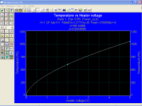
You can see that if 2 V filament energisation results in 604 K temperature as you claimed, the best fit line is very close to linear.
Do you want to cheat us with a poorly made plot???
Here is my plot, made with the appropriate software
Clearly, the relation it is not linear.
Attachments
Last edited:
The reason why the measured current veers away to the right of the langmuir V^3/2 line is due to the construction of the 1T4. The filament strand is 22 mm long. The anode and grids cover most of it, 18 mm. However, while most of the filament heat is lost be radiation to the anode and grids, some is lost by conduction to the filament support structure. This causes the temperature to be low at the ends.
Keit, emission is a statistical phenomenon, so uneven temperature distribution does not care, except perhaps to determine cathode temperature with Stefan-Boltzmann law.
See the datasheet for yourself
http://frank.pocnet.net/sheets/093/1/1T4.pdf
In triode connection nothing happens, even at “high” voltages; even with the control grid positive most valves have the same behavior like your 1T4, the effect has nothing to do with uneven cathode temperature distribution.
Even more, the 5R4GY has worse uneven cathode temperature distribution, if you were right, my plots should show the same effect, or worse, but it does not happens.
That is the opposite of what your set of plots show. One reason why I supect your "measurements" are dodgy or faked.
My measurements were done at the University lab, a long ago, and they were supervised by true physicists, even more, my work was approved as outstanding.
If you want, you can come here and see for yourself, free hosting, you only must pay plane tickets and share food costs.
The field due to the space charge is superimposed on the field established by the "anode" (anode plus grids). As the "anode" field gets stronger, it pulls the space charge way from the filament right enough, but that just means the space charge field is more spread out.
Amazing! You are right! Note that I said the electric field E, i.e. the total field, we agree, at last!
Why you thought I used base-10 logarithms is a mystery to me. But it doesn't matter whether you plot a graph with base1- logs or base-e logs, the progression up the axis is the same.
Pure nonsense, as ever, I do not bother to explain you again the same thing, it does not make any sense because you will not understand.
This plot is based on the thermal radiation law P = A.e.s(Tk^4 - Ta^4) and Fourier's Law of heat conduction
With non uniform temperature distribution, Stefan-Boltzmann law does not apply, only Fourier's law.
With non uniform temperature distribution I mean that temperature must be constant over the entire surface.
So your graph has only artistic value.
Last edited:
{Keit: Under a retarding field, most electrons return to the cathode}
That’s an indicator of your understanding of the experiment, if it were so, the method would be useless...without electrons you have no current…
It is blindingly obvious that most return to the cathode. They sure don't all go to the anode. Under retarding field conditions the anode current is microamps to picocamps, as you know perfectly well.
You are misquoting me…again...🙄
Yes, under a retarding field, most electrons return to the cathode. Virtually all, in fact,…
That’s an indicator of your understanding of the experiment, if it were so, the method would be useless...without electrons you have no current…
It is simple notation; unfortunately, K is the suffix for “Kilo”, i.e. 1 K = 1 x 10³
I don't give a toss what books or papers can say on this matter, I will still using ºK.
The prefix for kilo not K. It's k. Under internation metric standards, IUPAC etc, you don't write kilovolts as KV, you write it as kV.
Thus you can have kK, which means kilokelvin. Not a unit that has much use of course.
You confuse max allowable current with saturation current density, aka Jo, see for yourself at the RCA datasheet, page 3
There is no confusion. Max allowable PEAK current is 0.625 A per plate, 1.3 A total. It aligns to the industry rule of thumb that for reasonable life AVERAGE current should not exceed 40% of the saturation value, and peaks obviously must not exceed the saturation value.
That's why the saturation current in a rectifer should be just a bit bigger than the allowable peak current.
Now you confuse saturation current with heater current!!!
The saturation current is approx 1.5 A, 2 A tops. It is sort of a coincidence that the maximum likely saturation current is about the saem as the filament current.
I say "sort of", because all directly heated oxide tubes have roughly similar ratios of saturation current to heater power. This has to be so if the work function is about as good as can be achieved.
5R4GY: filament power 10 W; Saturation current 1.5 A; 150 mA/W
Thus if the 5R4GY was designed for 1.4V, its heater current would be 7.14 A.
1T4: filament power 70 mW; saturation current 15 mA; 214 mA/W
The better ratio for the 1T4 reflects that the design is better optimised to save battery current.
The tube industry has long had a rule of thumb that a tube shoukld be operated with an average current not exceeding 40% of the saturation value however this rule is relaxed for rectifiers, partly becasue narrow pulse operation suits oxide cathodes better, and it was always accepted that rectifier have a shorter life than signal tubes. Thus we can scale up from the max permitted 5R4GY average current rating (250 mA) we get roughly 1.5 A.
Clearly, my estimate of saturation current for the 5R4 is reasonable. The saturation current is certainly not 70 amps.
At saturation, current is enormous, but let me make a more refined calculation
For BaO-SrO
e φ = 1 eV ,….., Ao = 1 A/(cm² ºK²)
Then, at T=1050 ºK, directly from Richardson-Dushman equation
Jo ≈ 17.47 A/cm²
Or, if you want, Io ≈ 69.88 A
If you think a 5R4GY can pass 70 amps, you need a psychiatrist. You're having delusions!
using the expression for Child-Langmuir law, we can estimate the transition point before saturation
Vt = [(9 d² / 4 εo) √ (m / 2 e) Jo]^(2/3) ≈ 1777 V
That is a calculation erected upon a garbage input.
A 5R4GY cannot pass anything like 70 A, and it won't pass 3.4 A either, at any temperature below normal operation.
Do you want to cheat us with a poorly made plot???
Here is my plot, made with the appropriate software

Clearly, the relation it is not linear.
You've really messed up now, Popilin.
Your plot starts at absolute zero. It should start at 300 K, ie ambient temperature.
Unless you believe that a vacuum tube with no electrical input acts as a refrigerator and cools itself down to abolute zero!
You can't do anything right, can you?
Of did you think nobody would notice the curve starting at 0 K?
Its basic algreba. To go from 300 K (27 C) to 604 K at 2 V means a slope of 152K per volt. Similarly, to go from 604 K to 1050 K at 5 V means a slope of 148 K per volt. Very very close to a straight line. Within 0.67%.
I have explained this in various simple ways now. It is hard to believe you don't understand it, so are you trying to trick the readers of this thread?
Last edited:
You've really messed up now, Popilin.
Your plot starts at absolute zero. It should start at 300 K, ie ambient temperature.
Yes, you are right, at that time it was cold here, but not that much. 😛😀
With non uniform temperature distribution, Stefan-Boltzmann law does not apply, only Fourier's law.
With non uniform temperature distribution I mean that temperature must be constant over the entire surface.
So your graph has only artistic value.
What rubbish you write!
Use the whole statement:
It's valid to apply P = A.e.s(Tk^4 - Ta^4) to each small segment in turn, as the segment size is chosen so that the whole segment is, within required accuracy, equal to its median temperature.This plot is based on the thermal radiation law P = A.e.s(Tk^4 - Ta^4) and Fourier's Law of heat conduction (the heat equivalent of ohms law) and electrical dissipation P = I^2xR, evaluated for each of a set of small segments that in total comprise the whole filament.
Incidentally, the Stefan Boltzmann law is simply P = A.e.s.T^4 and describes radiation into free space.
P = A.e.s(Tinner^4 - Touter^4) is derived from the Stefan-Boltzmann law and descibes radiative heat transfer from one object to another that encloses it.
For a person who claimed to have worked under university physicists and got work accepted, you sure are sloppy. Do you call a truck a car?
Last edited:
Yes, you are right, at that time it was cold here, but not that much. 😛😀
So you are not going to mount a ridiculous challenge to that one? I'm dissapointed. So how about taking another look at all the other mistakes of yours that I have pointed out?
You are misquoting me…again...🙄
Originally posted by Keit:
It is blindingly obvious that most return to the cathode. They sure don't all go to the anode. Under retarding field conditions the anode current is microamps to picocamps, as you know perfectly well.Originally posted by Popilin:
That’s an indicator of your understanding of the experiment, if it were so, the method would be useless...without electrons you have no current…
This is really very simple.
It's a situation where something like 30 billion electrons per second are thrown out of the cathode by virtue of its' raised temperature. Due to the retarding field, only a few million per second make it to the anode. So 30 billion less a few million get turned back and re-enter the cathode.
The few million that make it to the anode get measured as a current on your picoammeter.
If there is an accelerating field (ie positive anode) billions of electrons are available and do reach the anode. If the anode voltage is well above saturation, virtually all of them get to enter the anode.
It is you, Popilin, who does not understand thermionic emission.
If the cathode is hot enough, electrons get thrown out into the space by their thermal velocity, per the Richardson-Dushman equation. They are hot enough to overcome the work function, so off into the space they go. When they get into the space, they can either be turned back or hurried on to the anode, depending on the magnitude and strength of the electric field in the space.
It's much the same as the kinetic theory of gasses. In fact it is the same - electrons form a gas - except they carry a charge. If you heat a solid substance, atoms/molecules leave the surface (having overcome the "barrier" of heat of sublimation) and go flying about in random directions and temperature driven velocity until collision with something, and nothing prevents that flying about.
Keit, emission is a statistical phenomenon, so uneven temperature distribution does not care, except perhaps to determine cathode temperature with Stefan-Boltzmann law.
Obviously, the temperature profile matters a lot. A heck of a lot. Each small part of the filament saturates at a current that is determined by the Richardson-Dushman equation, in accordance with the local temperature of that part.
If the anode voltage is low enough (and/or the grid sufficiently negative), no part of the filament is at saturation, and all parts contribute equally to the anode current (exceptin RF tubes with variable pitch control grids).
If the anode voltage is raised (or grid made less negative), saturation begins at the ends, and moves toward the centre as the anode volatge is raised. When the tube is fully saturated, all parts of the filament do NOT contribute equally to the anode current. Al higher portion comes from the centre.
In some diodes, a different phenomena occurs. For example the noise diode A2087: The filament extends well past the anode ends. The anode is quite short compared to diameter, in contrast to a typical rectifer. So the temperature profile of the filament that is within the anode is pretty even, even for a few mm outside the anode. But the electric field flux bulges out at the ends and spreads a little way along the filament towards the ends. So when anode volatge is progressively raised to bring an A2087 into saturation, saturation should begin at the centre of the filament and move outward to the ends.
Further, the A2087 filament is actually two strands that make a V-shape. So the top of the V is closer to the anode than the other end. So the electric field is stronger at one end and weaker at the other.
So, combining the two effects, saturation actually begins at one end (the top of the V), and as voltage is progressively raised, moves toward the other end, slowly at first due to opposition from end flux bulge out, and then faster as it gets well into the anode, and faster still when it gets closer to the other end.
All in all, a false schottky effect curve, until the whole length is thoroughly saturated.
Exactly. One of the reasons why I don't believe your plots are genuine.Even more, the 5R4GY has worse uneven cathode temperature distribution, if you were right, my plots should show the same effect, or worse, but it does not happens.
Oh, I see. Now it is revealed - you did this "a long time ago". And you still have your lab notebook, do you? And/or remember it perfectly?My measurements were done at the University lab, a long ago, and they were supervised by true physicists, even more, my work was approved as outstanding.
This is like when you cited a reference and implied you copied a graph from it. Then it was revealed the reference has no graphs, and you had not even accessed it.
You are a faker, Popilin. Your credibility is destroyed.
{Popilin apparently believes a graph scale in a logarithmic progression varies in progression depending on the logarithm base}
Pure nonsense, as ever, I do not bother to explain you again the same thing, it does not make any sense because you will not understand.
You claim to have done university physics, but you don't even understand logarithmic progression. Ever seen a slide rule? Everybody technical had them before calculators came on the market. Slide rules had a log scale - usually marked as a base-10 scale but sometimes (if the rule was for physicists and engineers, and not school children) a base-e scale. The carriage had a mark to one side of the main indicator line. If you had a base-10 rule and wanted a base-e result, you just used the offset line of the carriage. This performs the multiplication x0.4343.
In other words, a base-e scale is just a base-10 scale moved along a fixed distance. If the actuall markings are the primary quantity (as in a voltage scale in logarithmic progression), then it is just a logarithmic scale - neither base-10 nor base-e, nor base-anything else.
Last edited:
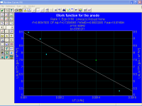
As most errors come from estimates based on Richardson-Dushman equation with data collected from tables, it is necessary to measure the Richardson constant.
In measurements with retarding potentials we must take into account that between anode and cathode exists a contact potential
φc = φa – φk
Then
Jr’ = Ao T² exp [ - e ( φk + Vr + φa – φk ) / k T ] = Jo’ exp ( - e Vr / k T )
With
Jo’ = Ao T² exp ( - e φa / k T )
Then, we can determine Ao from the straight line
Ln ( Jo’ / T² ) = - ( e φa / k ) ( 1 / T ) + Ln ( Ao )
Also we can determine Jo’ from the straight line
Ln ( Jr’ ) = - ( e / k T ) Vr + Ln ( Jo’ )

From the graph
Ao = (0.11 ± 0.01) A/(cm² ºK²)
Gentlemen, this explain all, this value differs by an order of magnitude with those from tables.
In measurements with retarding potentials we must take into account that between anode and cathode exists a contact potential
φc = φa – φk
Then
Jr’ = Ao T² exp [ - e ( φk + Vr + φa – φk ) / k T ] = Jo’ exp ( - e Vr / k T )
With
Jo’ = Ao T² exp ( - e φa / k T )
Then, we can determine Ao from the straight line
Ln ( Jo’ / T² ) = - ( e φa / k ) ( 1 / T ) + Ln ( Ao )
Also we can determine Jo’ from the straight line
Ln ( Jr’ ) = - ( e / k T ) Vr + Ln ( Jo’ )
From the graph
Ao = (0.11 ± 0.01) A/(cm² ºK²)
Gentlemen, this explain all, this value differs by an order of magnitude with those from tables.
Attachments
As most errors come from estimates based on Richardson-Dushman equation with data collected from tables, it is necessary to measure the Richardson constant.
And why, pray, do we need to measure it? For what purpose?
Certainly not to determine the saturation current at any desired temperature. I explained why in my post #376, and in different words, in other earlier posts.
I2 = I1 x [T2/T1]^2 x e^[{W/kB} {(T2 - T1)/(T1 . T2)}] ........(eqn 1a)
We have one equation (eqn 1a) that take takes what we know, conditions and saturation current at one temperature, and gives us the sat current at another temperature. We don't need to know the emission area or the Richardson constant for the emission surface.
All we need, apart from the saturation current at one temperature (the normal operating temperature, 1050 K), is the work function, W. And incidentally, you've been using a value somewhat too good for RCA tube designs. What can be achieved with carefull work is not necessarily what is actually achieved in volume production, which is all about repeatability, engineering margins/tolerances, using existing machinery where possible, and making money.
The RCA engineering manuals describe several cathode coating mixes standardized by them. The best of which from a work function point of view achieved no better than 1.76 x 10^-19 J. (C-185 mix, BaO+SrO+CaO 57:39:4)
Equation 1a is fortunate, as without examining a 5R4GY, which I suspect you don't even have now, we don't know the emission area either. I know you claimed to know the area in previous posts (4 cm), but is it correct? What is the source of this data?
From the graph
Ao = (0.11 ± 0.01) A/(cm² ºK²)
Gentlemen, this explain all, this value differs by an order of magnitude with those from tables.
You don't specify which tables. However, whatever tables you consulted, surely you would have learnt by now that if your result differs significantly from a published result or someone else's result, you'd stop, and think maybe you got it wrong? Or the accuracy of your measurements is simply not up to it? What was the condition of the tube you supposedly tested?
Last edited:
Keit, emission is a statistical phenomenon, so uneven temperature distribution does not care, except perhaps to determine cathode temperature with Stefan-Boltzmann law.
Obviously, the temperature profile matters a lot…
Pure nonsense, see the datasheet…again
http://frank.pocnet.net/sheets/093/1/1T4.pdf
As you tied the control grid and screen grid to anode, the effective distance cathode-anode was greatly reduced; at low anode voltages everything is close to normal, at about 10 V to 12 V, the electron cloud is moved toward the grid plane reducing the electric field E, the potential minimum which is normally at or very close to the cathode moves over in the direction of the grid plane, meanwhile the grid has low effective area and then most electrons pass and enter into the grid-anode region; inside this region the electric field almost vanished, but the suppressor grid is at the same potential than the cathode, inverting the direction of the electric field between control grid and suppressor grid, this produces another electron cloud, as a result the current is reduced until the voltage reaches about 18 V to 20 V, only then valve operation becomes to normal and once the electron cloud is depleted saturation is reached.
This has nothing to do with uneven distribution of cathode temperature.
Popilin, can you explain why the plot diverges away from the langmuir law between about 10 V and 12 V? I bet you can't - it's quite simple but it requires a real understanding of tubes and their construction.
Real understanding of tubes and their construction… 😛😀
For the next puzzle, be sure to have the correct answer. 😀
Exactly. One of the reasons why I don't believe your plots are genuine.
If you want, you can come here and see for yourself, free hosting, you only must pay plane tickets and share food costs.
My offer still stands.
Oh, I see. Now it is revealed - you did this "a long time ago". And you still have your lab notebook, do you? And/or remember it perfectly?
I have all crude data in paper, I had them into a floppy disk, but it was damaged and I could save only a part.
Indeed I have three sets of retarding potentials data, made with different methods.
Your credibility is destroyed.
You twist my words and arguments, you present my equations as yours, you misquote my posts…and now you are the judge about credibility and honesty???
You claim to have done university physics, but you don't even understand logarithmic progression.
You do not have a shred of shame, I wasted my time trying to explain you n times that issue, so far you do not understand because your understanding of physics is reduced to mere arithmetic, so, keep your slide rule and your calculator as souvenirs, with your fingers is enough.
Last edited:
Posted by Keit:
Obviously, the temperature profile matters a lot.
Pure nonsense
It's very obvious.
If one part of the filament is relatively hot, it can emit lots of electrons.
If one part is relatively cool, it can't emit so many electrons.
Hence saturation starts in the cooler parts (because in those parts there are no more electrons to be sucked into the anode) and moves into the hotter parts as the anode voltage is increased.
And just what are we supposed to get from the datasheet? The relavent bit is where it states the maximum permitted steady state cathode current, 5.5 mA. Note that the RCA datasheet for the 1T4 gives the maximum steady state cathode current as 6 mA.
In accordance with the tube industry norm that a tube should be operated at no more than 40% of the saturation current, the saturation current for this tube is thus 6/0.4 i.e., 15 mA. As I stated previously.
As you tied the control grid and screen grid to anode, the effective distance cathode-anode was greatly reduced; at low anode voltages everything is close to normal, at about 10 V to 12 V, the electron cloud is moved toward the grid plane reducing the electric field E, the potential minimum which is normally at or very close to the cathode moves over in the direction of the grid plane, meanwhile the grid has low effective area and then most electrons pass and enter into the grid-anode region; inside this region the electric field almost vanished, but the suppressor grid is at the same potential than the cathode, inverting the direction of the electric field between control grid and suppressor grid, this produces another electron cloud, as a result the current is reduced until the voltage reaches about 18 V to 20 V, only then valve operation becomes to normal and once the electron cloud is depleted saturation is reached.
Did you make this up as you went along? It certainly sounds like it.
Under normal operation, the screen sets up the electric field that accelerates space charge electrons to the anode. The suppressor grid does not much oppose this as it is wound with a much coaser pitch than the screen. As electrons pass through the screen, they have reached almost their ultimate velocity and inertia carries them on to the anode.
Those that strap up pentodes to act as triodes know they work just fine. Even in pertodes that have the suppressor internally connected to cathode, whether you like it or not.
In the 1T4 and pentodes generally, the control grid is MUCH closer to to the filament than the screen grid. So when the grid and screen are tied to anode, the accelerating field is almost completely set by the control grid. And that field is intense, because of the close spacing. So space charge electrons are at almost full velocity when they stream through the control grid. As the screen is at the same voltage, there is minimal further acceleration. The suppressor grid does not decelerate them any more than it does in normal operation as a pentode.
Except, as I said previously, at the ends of the filament. The control grid pitch is coarse pitch here, so the space charge "sees" an electric field partly from the control grid turns and partly from the screen grid turns. Effectively it is like an equivalent grid a little further from the filament.
As the suppressor is ineffective in slowing electrons down (due to its very coarse pitch), there is very little space charge between the screen and the suppressor. And if there was, that would mean that some electrons would be turned back. They would naturally get captured by the screen, so the current is maintained - The suppressor grid in reducing the anode current increases the screen grid current. As the screen (and teh control grid) is tied to the anode, what was measured is the total.
Some electrons enter the control grid and the screen grid of course. So the two grids contribute to the total "anode" current.
Tell someone who cares. I'm certainly not going to go halfway round the world at my expense just for this. And you know that, so your offer to host is meaningless.My offer still stands.
Oh, I see. Bit by bit it is revealed that the tests were:-I have all crude data in paper, I had them into a floppy disk, but it was damaged and I could save only a part.
a) done "a long time ago"
b) Data has been lost.
c) Details of experimental method is unknown, probably lost.
Really?Indeed I have three sets of retarding potentials data, made with different methods.
What were the three different methods then?
Your credibility is gone. But you'd have a little more credibility if you had told us what the three methods were, up front. You never did and you still haven't.
But you did say you used only a power supply, two multimeters and a picoammeter. With that, you could only have done some minor variant of a static retarding field test. The most useless of all the methods that have been devised by early workers and later ones such as Hienze & Haro, Sentara, Ikehara, etc.
You twist my words and arguments, you present my equations as yours, you misquote my posts…and now you are the judge about credibility and honesty???
You do not have a shred of shame, I wasted my time trying to explain you n times that issue, so far you do not understand because your understanding of physics is reduced to mere arithmetic, so, keep your slide rule and your calculator as souvenirs, with your fingers is enough.
Ahah! You have resorted to pure personal attack. Usually the recourse of someone who is unable to mount a reasoned logical argument.
Where exactly has I misquoted you? I note though that several times you have selectively quoted me so as to mislead.
You have demonstrated ability to copy formulae out of a book, but when it comes to actual calculation, you stumble badly. For example, that 604 K figure. And your claim that a 5R4GY can pass 70 amps. And more.
You have a nerve claiming equations as your own. Especially as you cannot use them to caculate correct answers. They are neither yours nor mine. They are the equations of the people thay are named after.
I used only simple 1st year high school algebra because that was all that was needed. I note that at no time did you identify any fault with my algebra.
Last edited:
 this thread has turned into a ******* match, get yourselves a break.....
- Status
- Not open for further replies.
- Home
- Amplifiers
- Tubes / Valves
- Why Gold Grids