The 7.5 mA was not my estimate. It was your "measurement".As your super duper planar diode can grow up from 5 mm to 20 mm anode-cathode spacing, your estimate for saturation current also can grow up from 1 mA to 7.5 mA.
Besides this is not a calculation but a guess, it is wrong.
Cathode temperature, measured with retarding potentials, at 2 V
T = (604 ± 25) ºK
Far away {from} your guessed 780 ºK
You've fallen into a deep well you dug yourself, Popilin.
If it is only 604 K, then the emission would be even lower, and your "measured" current of 9 mA even more too high - way way too high.
Stick 604 K into the R-D equation and see. Its about 160 uA. So your "measurement" is two orders of magnitude out based on your temperature.
You have some explaining to do.
My Goodness! Again with this nonsense!
Let’s suppose an Ia vs Va plot, way before saturation obviously it must follow the 3/2 power law, i.e.
Ia = Co V^(3/2)
Then
Ln(Ia) = (3/2) Ln(V) + Ln(Co)
It is not a 3/2 power law anymore!!!

So what! You don't get it do you? A straight line in a log-vs-root plot is almost a straight line in a linear plot over most of the range. In a log plot the visual effect is that the transition from Langmuir to Schottky lines moves to the right, but the langmuir line still departs from the origin at a marked angle. Not vertical like in the plot you "naively" posted several times.
It should be obvious to you that the plot is wrong. Not just a case of sloppy draftmanship, its seriously wrong.
Why are you still defending it anyway? You are only making yourself look silly. It has been established you didn't get it from the Nottingham refrence you cited. It's best forgoten about.
Anyway, if you do not like the plot, I have another 😀😀
Yeah - another graph from another source we cannot access on line. Without the asscociated text as usual.
You would have more credibilty if you posted the whole page, or a couple of pages if they have relavent text.
After all that repeated stuff you've posted, and it being exposed you never even consulted the reference you cited, you have zero credibility now, Popilin. All you've demonstated, repeatedly, is an ability to copy out formulae without understanding, and inability in reading Ia vs Va graphs, and dishonesty in citation.
Go back under your bridge and join the other trolls.
Unless you can answer the question I put to you in a couple of posts, including #329. Just about any engineer with tube experience could readily furnish the answer, but I bet you cannot.
The 7.5 mA was not my estimate. It was your "measurement".
Someone lies, only need to know who.
My measurement
From the last plot
Ln(io) ≈ 8.77 µA
Then
io ≈ 6.44 mA
I will refresh your memory
Using the Richardson-Dushman equation, we can start with the upper estimate of saturation current (2 A) at Vf = 5 V and see what it would be at Vf = 2 V. It turns out to be about 1.3 mA, not 7.5 mA. More likely about 1 mA.
You silly moo, Popilin, by doing it "correctly" as per your posts, you get an answer for saturation current slightly bigger than my estimate of 7.5 mA.
This establishes that your "measured" value is a bit less likely to be reality.
As I said before, your estimate for saturation current grows up from 1 mA to 7.5 mA.
Lack of honesty… 🙄
You've fallen into a deep well you dug yourself, Popilin.
If it is only 604 K, then the emission would be even lower, and your "measured" current of 9 mA even more too high - way way too high.
Stick 604 K into the R-D equation and see. Its about 160 uA. So your "measurement" is two orders of magnitude out based on your temperature.
You have some explaining to do.
Wrong…again.
You are still throwing dice… 😀
With the data from here
https://www.google.com/url?sa=t&rct...sg=AFQjCNGnTM8R-BBTzwUFLvCL5R7fC5YFBQ&cad=rja
For BaO-SrO
e φ = 1 eV ,….., Ao = 1 A/(cm² ºK²)
Then, at measured cathode temperature
T = (604 ± 25) ºK
Jo ≈ 1.65 mA/cm²
Measured cathode area
Ak = (4 ± 0.4) cm²
Then, finally
io ≈ 6.6 mA
Very close, right? 😎
BTW, measured work function for the cathode
e φ = (0.9 ± 0.2) eV
It is not too bad. 😎
So what! You don't get it do you? A straight line in a log-vs-root plot is almost a straight line in a linear plot over most of the range. In a log plot the visual effect is that the transition from Langmuir to Schottky lines moves to the right, but the langmuir line still departs from the origin at a marked angle. Not vertical like in the plot you "naively" posted several times.
It should be obvious to you that the plot is wrong. Not just a case of sloppy draftmanship, its seriously wrong.
Why are you still defending it anyway? You are only making yourself look silly. It has been established you didn't get it from the Nottingham refrence you cited. It's best forgoten about.
Does not matter how many times I explain to you the same thing, you will not understand.
During my trip, I explained the issue to my wife, curiously she understood it perfectly.
Then you must explain how a housekeeper can understand something that an electronic engineer cannot.
Meantime, you will be punished with...more plots! 😀
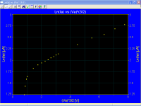
Typical plot Ln(Ia) vs √Va, 5R4GY, 1 V heater voltage
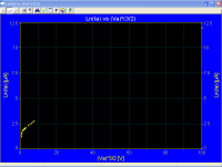
The same plot with a false point in order to change the scale factor
Yeah - another graph from another source we cannot access on line. Without the asscociated text as usual.
You would have more credibilty if you posted the whole page, or a couple of pages if they have relavent text.
Something more “relavent”
Let me google that for you
Sorry Keit, I am destroyed after the trip, tomorrow I will think about the rest of your puzzle.
Attachments
OK, Phys. Rev. 49, 78 (1936) seems much more like it. It's actually quite a long paper (pages 78 to 97), and it has 19 plots, with quite a few showing Schottky current against voltage. (Actually, log(current) vs. sqrt(voltage).)
Chris
Thanks!
Then, this paper is a good candidate for the mystery plot
Phys. Rev. 49, 78 (1936) - Thermionic Emission from Tungsten and Thoriated Tungsten Filaments
We know who. It's you. You are the one who claimed to have extracted a plot from a paper by Nottingham, and later it was revealed that you had not.Someone lies, only need to know who.
As I said before, your estimate for saturation current grows up from 1 mA to 7.5 mA.
You are trying to mislead people again.
Kindly cease quoting out of context.
You know perfectly well that the 7.5 mA figure is the figure I got from projecting back a schottky line on the first plot you posted, which you later (much later) claimed to be based on measurements you did on a 5R4GY at 2 V heater energisation. It is a linear axes plot. My estimate from your plot.
My estimate of the 2 V saturation current based on the Richardson-Dushman equation, the standard work function value for RCA directlly heated oxide cathodes, and standard tube industry rules of thumb on standard current at nominal heater voltage was and is 1mA, upper limit 1.3 mA. There has been no "growing up".
You insisted that it should be done on a log(Ia) vs root(Va) basis. So in post #337 I estimated from your same plot, on the basis of a best fit schottky line considered as that passing thru the current at 20 V (root Va = 4.472, Ln(Ia) = 2.251 ) and 60 V (root Va = 7.746, Ln(Ia) = 2.565). Then by simple proportionality of logarithms, Ia at 2 V is 9.1 mA according to your plot. This method is mathematically the same as drawing a schottky straight line on an actual log vs root plot.
So, as I said before, your "measurement" is somehat more unlikely by using your method, not less.
Which is a dead link. We've come to see that that is typical of you.
That value is wrong, but it doesn't matter as Ao cancels out in the calculation if you do it right. That is, use the 5V conditions to work out Ao x area (a constant specific to the tube) and then use that to calculate sat current at 2 V.For BaO-SrO
e φ = 1 eV ,….., Ao = 1 A/(cm² ºK²)
I did explain that before. Looks like you didn't understand it.
Then, at measured cathode temperature (at 2 V)
T = (604 ± 25) ºK
I note that you did not say how you measured it.
The standard operating temperature for RCA oxide cathodes is 1050 K. The anode will run at about 700K - the exact value is unimportant here due to the ^4 terms. The standard RCA (& American manufactuers generally) filament wire is J-wire but may be pure tungsten for a high spec rectifier. Both comply very closely to Worthing's formula. Resistance is approx proportional to absolute temperature.
So, we can use an approximate method to find out if your 604 K is realistic.
At 5 V filament energisation, from the grey body radiation loss formula,
P = k (Tf^4 - Ta^4) = 10 W = k (1050^4 - 700^4) hence k, a constant comprising the product of area, emissivity, & Stefan Boltzmann constant, is equal to 1.035x10^-11 W.K^-4.
At 2 V filament energisation, taking your 604 K temperature as correct, since resistance is approx proportional to temperature, power is approx P = V^2 x 2/5 x 1050/604 = 2.78 W.
At 2 V, anode temperature will be near ambient - again the exact value is quite unimportant. From the grey body equation:-
P = k (Tf^4 - Ta^4) = 1.03x10^-11 . (604^4 - 300^4) = 1.28 W.
1.28 W heat out (derived from your temperature) is along way from 2.78 W electrical input. Clearly the temperature is much greater than your claimed measurement.
In practice there is a few percent of the heat lost be conduction via the filament leads, but the above approc calc clearly establishes that you got the temperature very wrong.
In practice, the resitivity of J-wire or tungsten is not precisely proportional to temperature. The Worthing exponent for tungsten is 1.203. This means that the approx method I explained above actually underestimates a little the electrical input to the filament at 2 V.
If the filament is nickel tape (not likely in a 5R4GY), your temperature guess is still impossibly low. Nickel is ferromagnetic, with a curie point at 630 K. Above that the tempco is sharply reduced.
Hence, your calculation of Jo is worthless.
Well, she may have said she did. It is the well known job of wives, as understood by wives, to say whatever the wife thinks the husband wants to hear. It means nothing.During my trip, I explained the issue to my wife, curiously she understood it perfectly.
Who cares what your wife says anyway. Readers of this thread don't know her. We don't know what you explained to her. We don't even know if you have a wife.
Last edited:
Keit,
The link isn't dead because i just downloaded it.
Quote:
Originally Posted by popilin View Post
With the data from here
https://www.google.com/url?sa=t&rct=...C5YFBQ&cad=rja
Which is a dead link. We've come to see that that is typical of you.
The link isn't dead because i just downloaded it.
Quote:
Originally Posted by popilin View Post
With the data from here
https://www.google.com/url?sa=t&rct=...C5YFBQ&cad=rja
Which is a dead link. We've come to see that that is typical of you.
Keit,
The link isn't dead because i just downloaded it.
It's dead to me. If I click on it, I get the following message in a new browser window:
Redirect Notice
The previous page is sending you to an invalid url.
And I can go neither forward nor back in that window - No previous page is available.
If it works for you, would mind posting any one or two pages that seem relavent?
I did. It doesn't work. Still doesn't work. If it doesn't work for me but does for you, chances are it doesn't work for many others.
If it works for you, please post whatever 1 or 2 pages seem appropriate, and help us out.
Very rarely, a link works in one country or internet service provider (ISP) but not in another because one country or ISP hasn't got the right map translating urls to IP addresses for some reason. Or, also very rarely, a server is blocked by an ISP because they detected malware (or thougfht they did) or there is government imposed blocking.
Last edited:
http://www.springer.com/cda/content...6286681-c1.pdf?SGWID=0-0-45-563605-p173754903
I can not do more then this. I have checked it and it works here at my place
I can not do more then this. I have checked it and it works here at my place
I can do more: post the whole thing on the forum. If the moderators find it inappropriate, they can always remove ithttp://www.springer.com/cda/content...6286681-c1.pdf?SGWID=0-0-45-563605-p173754903
I can not do more then this. I have checked it and it works here at my place
Attachments
works from sweden toohttp://www.springer.com/cda/content...6286681-c1.pdf?SGWID=0-0-45-563605-p173754903
I can not do more then this. I have checked it and it works here at my place
You are trying to mislead people again.
No, almost from the beginning you are confusing people with your nonsense. 🙄
Which is a dead link. We've come to see that that is typical of you.
No, the link woks fine.
You ever have an excuse…
Yeah right, Popilin. Turns out that is a site listed by MacAfee as malignant. MacAfee will not aloow my PC to acess it.
That value is wrong, but it doesn't matter as Ao cancels out in the calculation if you do it right.
Let’s advise people that Richardson's constant is useless...

I note that you did not say how you measured it.
Yes I did, anyway if you insist…
Applying a retarding potential, Vr
Jr = Ao T² exp [ - e ( φ + Vr ) / ( k T )] = Jo exp ( - e Vr / k T )
Then you can obtain cathode temperature, T, from the slope of the straight line
Ln (Jr) = - ( e / k T ) Vr + Ln (Jo)
Or
Ln (Ia) = - ( e / k T ) Vr + Ln (Io)
From the graph
We obtain
T ≈ 604 ºK
Attachments

Last edited:
This is bad physics. Ln(x) and sqrt(x) have different dimensions/units, and if they happen to share a numeric similarity over a limited range of values that is just a happy coincidence. The correct interpretation of gradient will always have correct dimensions, it's an easy check to make........A straight line in a log-vs-root plot is almost a straight line in a linear plot over most of the range.
This is bad physics. Ln(x) and sqrt(x) have different dimensions/units, and if they happen to share a numeric similarity over a limited range of values that is just a happy coincidence. The correct interpretation of gradient will always have correct dimensions, it's an easy check to make........
It's not a happy coincidence at all. Try it and see. Draw a plot using Log-vs-root axes, and replot the same values in linear axes. You'll find that straight lines in one are only slightly curves in the other. Hence "J" shapes as in the langmiur part of the graph in a linear plot is still a "J" shape in a log-vs-root plot, but the foot of the J is visually longer.
Using Popilin's linear axes plot, the 0 V intecept appers to be 7.5 mA. Try it and see. Doing it correctly, with log-vs-root values, it's 9.1 mA. So, yes, using a linear plot results in an error, but I was showing that Popilin's "measurement" is not believable. Only the order of magnitude is needed to do that.
Let’s advise people that Richardson's constant is useless...
There you go, misreading what I said again. Being silly again. I didn't say Richarson's constant is useless. I said that when calulating conditions for a tube operated at a low heater voltage, starting from the known conditions at normal voltage, the Richardson constant cancels out. Which it does if you do the calculation correctly. As I explained.
Applying a retarding potential, Vr
Jr = Ao T² exp [ - e ( φ + Vr ) / ( k T )] = Jo exp ( - e Vr / k T )
Then you can obtain cathode temperature, T, from the slope of the straight line
Ln (Jr) = - ( e / k T ) Vr + Ln (Jo)
..... etc etc
We obtain
T ≈ 604 ºK
The retarding field method is grossly inaccurate when applied to real tubes. You would know this if you have any lab experience with tubes. See Ikehara S, Journ. Appl. Phys. 23(6) p725, 1954.
I quote from the opening paragraph:-
"The static method of measuring the slope of the ordinary retarding potential curve resulting from the initial velocity distribution of the emitted electrons is not practical because it is liable to gross errors."
As proved in my post #344 where I calculated the electric input at 604 K and the heat output at 604 K. The two values should be about equal (within 10% or so) but they are clearly very different. You need to explain that one away, Popilin.
The text in Ikehara's paper then goes on to propose a claimed much better method, which seems never to have won industry acceptance.
How to accurately measure the cathode temperature in indirectly heated cathodes in working tubes frustrated tube factory engineers for decades.
The best way is by measuring the visual wavelength radiation via holes cut in the anode for the purpose (That's why you sometimes see holes in the anode - they are there to permit grid alignment checks and/or check cathode temperature), but as :-
# the absorption in the glass varies,
# the spectral emissivity of the cathode is not accurately known (chicken and the egg: To measure spectral emissivity, you need the temperature; to measure temperature you need the spectral emissivity),
-and-
# the process is mathematically a subtraction of two large values to get a small difference,
the method leaves a lot to be desired.
See RCA red book which covers the problems of measuring cathode temperature at length.
Fortunately, with directly heated tubes, you can measure the electrical resistance, apply Worthing's formula, and with some small corrections for conductive heat loss, it's quite accurate.
Last edited:
Re 5R4GY filament temperature, which Popilin says is 604 K at 2 V energisation:-
If Popilin was anywhere near as good with math/physics as he claims to be, he would have spotted something obvious:-
Given ambient temperature is approx 300 K, a filament temperature of supposedly 604 K at 2 V filament voltage, and the standard cathode temperature of 1050 K at normal voltage (5 V), it all implies that temperature varies directly proportionally with filament voltage. That cannot be.
Try it and see: 300 + (1050 - 300) x 2/5 = 600 K.
But due to the formula for radiated heat, wich arises from the Stefan-Bolzmann law, P = k (Tk^4 - Ta^4), and electrically, P is approx proportional to voltage (due to resistance rising with temperature), temperature is thus approx proportional to V^1/3.
So the relationship between temperature and voltage is nothing like linear. Tubes strongly regulate their own cathode temperature. Dropping the heater voltage to 40% of the normal value will thus result in a temperature way above 600 K. Something like 850 K by the above quick cube law estimate:
300K + (1050K - 300K) x (2/5)^1/3 = 850 K
In practice, its a bit lower than 850 K due to some conduction loss (proportionately higher cf radiation, at lower temperatures), resistance is not quite linear with temperature, and anode temperature will fall below the normal level, radiating back to the filament a bit less.
Popilin should have realised his 604 K cannot possibly be right as soon as he got it. It took 5 minutes to type this, but about 1/10th of a second to think it.
This is the sort of sanity check that good engineers and physicists do all the time. Not Popilin apparently.
I can do more: post the whole thing on the forum. If the moderators find it inappropriate, they can always remove it
Many thanks. The link provided by TrippleM works as well.
{Did not state how 604 K was arrived at}
Yes I did, ......
You came up with the 604 K value in your post #339
Cathode temperature, measured with retarding potentials, at 2 V
T = (604 ± 25) ºK
That's all you said about it. Clearly the "+,- 25" bit is entirely your imagination.
"measured with retarding potentials" is hardly setting out how you arrived at the temperature. How was it measured? With what equipment? There are several different methods derived from retarding field theory, all with varying degrees of none too good inaccuracy and various levels of test equipment complexity, eg the methods of Hienze & Haro, Sentaro, the sawtooth and AC methods of Takada, the harmonic method of Ikehara. Which one did you in fact use?
From the math you quoted, it seems you used the simple static (DC) method, which is the most hopeless method of all, as Ikehara stated in his 1953 paper. You did not, for instance, give any math for the harmonic method.
The 5R4GY is directly heated. Why one earth did you go for a complex inaccurate method (static retarding field plot), when you could have just measured the filament current, calculated the resistance from Ohm's Law, and then derived temperature from Worthing's Law. Quick, simple, and even without the tweak for conduction loss at the ends, sufficiently accurate for the purpose?
Your approach is the approach of someone who copies from books but has no actual understanding or experience. Or you are trying to impress rather than inform.
Last edited:
- Status
- Not open for further replies.
- Home
- Amplifiers
- Tubes / Valves
- Why Gold Grids