I believe enro borely used something like this circuit about 35 years ago..However he used a lf353 ic witha +- supply,,whick worked pretty good..This tlo71 is being used as a nulling device in this circuit,,and your vright the offset will rise very high without it..Also I would adapt the circuit with out this ic. Evette
Hi evette,
Thanks for the suggestions. You kept me going long enough to try a few things. I got a chance to hook this amp up to my A/B setup. I compared it to a VSSA, Symasym and the SKA GB150. It held its own well against all three but is closest sonically to the SKA. Nice amp,
Thanks for the suggestions. You kept me going long enough to try a few things. I got a chance to hook this amp up to my A/B setup. I compared it to a VSSA, Symasym and the SKA GB150. It held its own well against all three but is closest sonically to the SKA. Nice amp,
is closest sonically to the SKA.
Both M1 and SKA has high "drive" (whatever that means 😀)
Where are you up to Terry ? It sounds like you have it working 🙂
The feedback cap has around 6 volts across so make sure by measurement that you have it correct. The IC provides the DC bias for the input stage and it is a vital part of the design. Most servos operate around zero volts and just hold the final output at zero by giving a tiny correction. This one doesn't. It actually provides both the servo function and the bias voltage needed for the single ended input stage which is why the opamp output is at -6v or so. You could replace the opamp with a preset and bias the input to around -6 volts carefully trimming the preset to give zero volts DC at the output but that wouldn't be ideal because the offset would wander greatly with supply and temperature variations. The opamp hold the offset to within a millivolt or so of zero.
The feedback cap has around 6 volts across so make sure by measurement that you have it correct. The IC provides the DC bias for the input stage and it is a vital part of the design. Most servos operate around zero volts and just hold the final output at zero by giving a tiny correction. This one doesn't. It actually provides both the servo function and the bias voltage needed for the single ended input stage which is why the opamp output is at -6v or so. You could replace the opamp with a preset and bias the input to around -6 volts carefully trimming the preset to give zero volts DC at the output but that wouldn't be ideal because the offset would wander greatly with supply and temperature variations. The opamp hold the offset to within a millivolt or so of zero.
Hi Mooly,
Yes I can see that the servo is needed and it is doing a good job of keeping the offset stable at +-2mV or better. I don't understand how yours is working with the NFB cap set up with the -lead to ground. In that orientation the cap pulled the servo way off course. With the + lead to ground it is perfect.
The sound is nice even with the test PSU. Tomorrow I will hook up a stiffer PSU and give some extended listening. Thanks for all your help.
Blessings, Terry
The plus lead of the cap should be to ground 🙂
Where have you got the idea that mine is working with the minus lead to ground. You see the input transistor needs around -6 volts at the base to bias the amp correctly and give zero volts at the output. That means the emitter of the input device is around minus 5.4 volts. So ground that the cap returns to is 'positive' compared to the emitter, hence the reason the cap is fitted as it is. You've obviously got it correct as its all working and holding the offset to near zero. The offset you see is just the natural internal offset within the opamp and even that could be trimmed using the offset null facility on pins 5 and 8.
Well done though, I'm pleased someone else has constructed this.
I'm sorry I said that wrong. With the + lead to ground the amp would start with 30mV offset and tise to 15-20V offset within a couple minutes. Once I reversed the cap and made it - lead to ground the whole thing settled down and has been perfect ever since. To morrow I will measure the voltage at the cap and see what it is. I see on the sim that it is negative there but I'm telling you my amp was out of control with the cap the other way.
I'm still a little confused tbh 🙂
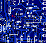
The board layout here is correct. You will find the emitter of the transistor that the cap goes to is at around minus 5.5 volts or so with respect to ground. The cap plus end then goes to the 470 ohm that goes to ground.
Its obviously correct as you have it or the amp just would not work. If your cap markings don't agree... 😱 I'd be looking at the cap and making sure its a genuine part.
Attachments
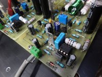
You are correct. That is the way the cap is marked on the board. That is how I initially had it and it would not work, Huge offset. I now have the cap the opposite of what is shown in your picture and the amp works flawlessly.
Here's a picture of the working board.
Here's a picture of the working board.
Attachments
Last edited:
Terry... you need to scrutinise those caps, there is something odd with them such as the sleeve being 180 degrees wrong.
If you measure the voltage across the cap then I think you will find the voltage doesn't agree with the cap markings. That is to say, with your red meter lead on cap plus and the black lead on cap minus then I think you are going to read minus 6 volts.
Another check on cap polarity is to measure the DC voltage across the 470 ohm. It should be 0.0000 volts with a good cap correctly fitted.
Please change those caps and fit new replacements as marked on the board.
Hi Mooly,
I will be take some measurements for you this morning. Didn't you read about all the trouble I was having with this amp?. With the cap fitted per the schematic, the more it charged up the farther off it pulled the offset. Once it reached a certain point the servo would start surging because it could no longer keep up. I suppose it could be something else that is causing the cap to charge up and this is just a symptom.
I will be take some measurements for you this morning. Didn't you read about all the trouble I was having with this amp?. With the cap fitted per the schematic, the more it charged up the farther off it pulled the offset. Once it reached a certain point the servo would start surging because it could no longer keep up. I suppose it could be something else that is causing the cap to charge up and this is just a symptom.
Yes, I did read all the posts. Please do the measurements I outlined on the cap.
The emitter of the first transistor should be around negative 6 volts give or take with respect to ground. That is why the negative end of the cap connects there, and the positive end to ground. The voltages on the simulation I showed yesterday are in the correct ball park.
Please do the measurements 🙂 I'll look in later.
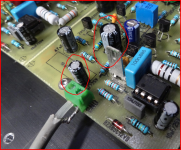
-3.6VTerry... you need to scrutinise those caps, there is something odd with them such as the sleeve being 180 degrees wrong.
If you measure the voltage across the cap then I think you will find the voltage doesn't agree with the cap markings. That is to say, with your red meter lead on cap plus and the black lead on cap minus then I think you are going to read minus 6 volts.
6mVAnother check on cap polarity is to measure the DC voltage across the 470 ohm. It should be 0.0000 volts with a good cap correctly fitted.
Please change those caps and fit new replacements as marked on the board.
With the cap fitted the way they are I have -6V on the output of the servo. With them fitted per the schematic I have -10.5V on the servo output. With the caps fitted the way they are I have basically zero offset. With them fitted per the schematic I saw as much as 27V offset. Now it may not be the cap that is causing the issue. It might just be that the cap being inverted is stopping the voltage at the emitter of Q1 from rising too high. Perhaps there is something else that is driving the offset to rise and the inverted cap is clamping it down. I don't know. What I do know is that it didn't work before and now it is. I don't mind trying different scenarios if you feel like doing to work but changing the cap back is not going to solve it though it may help reveal it. This is kind of tough with us living in drastically different time zones but I'm in no hurry. This is a hobby after all.
Blessings, Terry
Mooly is not suggesting to change the cap back to how it was, he is suggesting the sleeve of the cap has been fitted the wrong way round by the manufacturer. This does appear to be true going by your measurement. Where did you buy the cap from?
For peace of mind, swap the cap out for another totally different cap, but with polarity as marked on the PCB. The value is not critical as it is just a steady state test. It should produce a stable result.
For peace of mind, swap the cap out for another totally different cap, but with polarity as marked on the PCB. The value is not critical as it is just a steady state test. It should produce a stable result.
Last edited:
Terry, everything is pointing to those caps being marked with reverse polarity on their sleeve. As Richie says, the value isn't critical to prove this, even a 47uf or 100 uf would be OK.
Please just swap one and fit the replacement as marked on the board.
Please just swap one and fit the replacement as marked on the board.
Also, do you have the input coupling cap the correct way around ? Negative end to the transistor.
Changing the input cap fixed it. All is well.
I learned a big lesson today. I have never given much thought to the polarity of the input cap since most of the time it can be replaced with a NP. Thanks for staying with me on this and getting to the bottom of it. Hopefully it will be useful for others who may wish to build the amp. I'm going to try to give it a lot of listening time today. I like the size of the boards. Any reason why it won't handle +-60V rails with the 2 pair output configuration? Should I raise R27 to something higher than 10k?
Thanks, Terry
Last edited:
That's great. Now you can really give it a good listen 🙂 Those caps are both fitted differently to what you might expect given a quick look at the circuit.
-/+ 60 volts rails would possibly need Q3 and Q5 uprating or at least fitting with clip on heat sinks. They would certainly run hot and be dissipating around 400mw each at idle. The 10k should be fine as it is as long as a 0.5 watt part is fitted.
-/+ 60 volts rails would possibly need Q3 and Q5 uprating or at least fitting with clip on heat sinks. They would certainly run hot and be dissipating around 400mw each at idle. The 10k should be fine as it is as long as a 0.5 watt part is fitted.
- Home
- Amplifiers
- Solid State
- My MOSFET amplifier designed for music