How do you measure capacitance with a scope probe?
I don't doubt that they're genuine parts. Wima usually states the capacitance in picofarads and microfarads, you can look it up in their datasheets. I rather think that there's something off with how you got to your 1nF-result.
I don't doubt that they're genuine parts. Wima usually states the capacitance in picofarads and microfarads, you can look it up in their datasheets. I rather think that there's something off with how you got to your 1nF-result.
no...no
in post 2058 you wrote somthing noise in my probe of the output pin of the opv (TL071). the dark blue line is too noise.
that is why i wrote mybe i used a bad scope probe.
in post 2058 you wrote somthing noise in my probe of the output pin of the opv (TL071). the dark blue line is too noise.
that is why i wrote mybe i used a bad scope probe.

ic check the WIMA it si written 100/400V
measured 1nF !!
omg
and the amp has worked?!?
just to clarify
after a smal talk to my colleague he give me the hint that the cap Multimeter i used is defect.
so you are right it must be 100pF.
at home i veryfiy this with my LCR meter --> yes it is 100pF
it is a WIMA - FKP2G001001D00JSSD 100pF 400V 5mm pitch
Wima 100pF 400V
last check before l channel goes back into the amp.
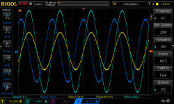
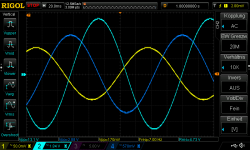
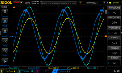
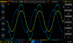
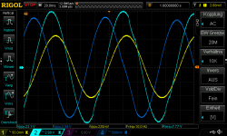
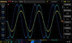
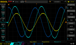
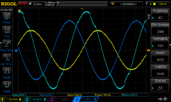
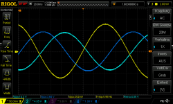
setup is 2,86Vrms without load and check the pin6 pov output to be sure everything is fine.
from 200Hz down
yellow ch1 is input
light blue ch2 output scope probe directly at the amp out
drak blue ch4 is the pin6 opv output
looks okay -its more then preamp-Lasse- suggested -
kr
chris
setup is 2,86Vrms without load and check the pin6 pov output to be sure everything is fine.
from 200Hz down
yellow ch1 is input
light blue ch2 output scope probe directly at the amp out
drak blue ch4 is the pin6 opv output
looks okay -its more then preamp-Lasse- suggested -
kr
chris
Attachments
-
 no load_1W_4Hz_input ch1_output ch2_pin6opv ch4.png56.2 KB · Views: 29
 -
 no load_1W_200Hz_input ch1_output ch2_pin6opv ch4.png58.3 KB · Views: 33
 -
 no load_1W_100Hz_input ch1_output ch2_pin6opv ch4.png56.3 KB · Views: 33
 -
 no load_1W_70Hz_input ch1_output ch2_pin6opv ch4.png63 KB · Views: 33
 -
 no load_1W_50Hz_input ch1_output ch2_pin6opv ch4.png58.8 KB · Views: 31
 -
 no load_1W_30Hz_input ch1_output ch2_pin6opv ch4.png60.6 KB · Views: 27
 -
 no load_1W_10Hz_input ch1_output ch2_pin6opv ch4.png54.7 KB · Views: 33
 -
 no load_1W_7Hz_input ch1_output ch2_pin6opv ch4.png50.2 KB · Views: 26
now it is with 8R load after the coil
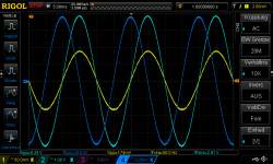
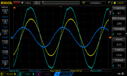
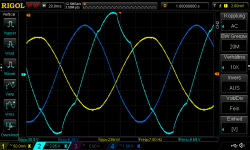
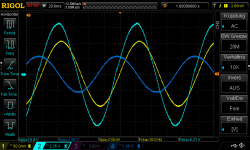
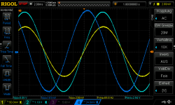
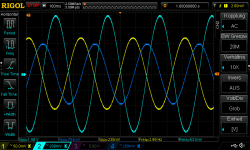
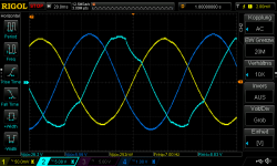
setup is 2,86Vrms with load and check the pin6 pov output
from 200Hz down
i got a spike!
at lower frequency it doesn help to set the current up of my psu ..its toggling around...
yellow ch1 is input
light blue ch2 output scope probe directly at the amp out
drak blue ch4 is the pin6 opv output
okay????
Attachments
-
 8R load_1W_200Hz_input ch1_output ch2_pin6opv ch4.png58.3 KB · Views: 33
 -
 8R load_1W_100Hz_input ch1_output ch2_pin6opv ch4.png52.8 KB · Views: 39
 -
 8R load_1W_70Hz_input ch1_output ch2_pin6opv ch4.png61.4 KB · Views: 35
 -
 8R load_1W_50Hz_input ch1_output ch2_pin6opv ch4.png56.6 KB · Views: 28
 -
 8R load_1W_30Hz_input ch1_output ch2_pin6opv ch4.png51.2 KB · Views: 37
 -
 8R load_1W_10Hz_input ch1_output ch2_pin6opv ch4.png57.6 KB · Views: 34
 -
 8R load_1W_7Hz_input ch1_output ch2_pin6opv ch4.png53.4 KB · Views: 39
at lower frequency it doesn help to set the current up of my psu ..its toggling around...
See if the glitch appears on the rails. If the PSU is doing strange things then that will reflect in the behaviour of the amp.
The output of the amp and the output of the opamp should be clean under sinewave testing under all conditions and loading. It sounds like you have either PSU issue or the grounding is incorrectly configured.
psu is clean..rigol 832..or not?
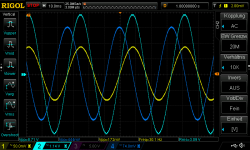
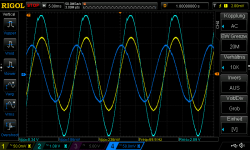
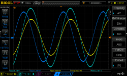
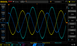
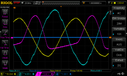
yes its getting better after i changed/repair completely the GND cables at my psu.
but stil between 10-7Hz strange
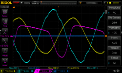
at 7Hz i use the ch3 pink to look at the negatie rail and positive rail.
i guess that the PSU is struggling with this load...still no constant voltage and current is up to 1A.
3,5,6Hz is gone
yes its getting better after i changed/repair completely the GND cables at my psu.
but stil between 10-7Hz strange
at 7Hz i use the ch3 pink to look at the negatie rail and positive rail.
i guess that the PSU is struggling with this load...still no constant voltage and current is up to 1A.
3,5,6Hz is gone
Attachments
-
 8R load_1W_10Hz_input ch1_output ch2_pin6opv ch4_2.png51.1 KB · Views: 25
 -
 8R load_1W_30Hz_input ch1_output ch2_pin6opv ch4_2.png53.7 KB · Views: 25
 -
 8R load_1W_50Hz_input ch1_output ch2_pin6opv ch4_2.png58.1 KB · Views: 23
 -
 8R load_1W_70Hz_input ch1_output ch2_pin6opv ch4_2.png53.3 KB · Views: 26
 -
 8R load_1W_100Hz_input ch1_output ch2_pin6opv ch4_2.png56.1 KB · Views: 30
 -
 8R load_1W_200Hz_input ch1_output ch2_pin6opv ch4_2.png53.1 KB · Views: 29
 -
 8R load_1W_9Hz_input ch1_output ch2_pin6opv ch4_2.png54.2 KB · Views: 25
 -
 8R load_1W_8Hz_input ch1_output ch2_pin6opv ch4_2.png53.3 KB · Views: 35
 -
 8R load_1W_3Hz_input ch1_output ch2_pin6opv ch4_2.png60.4 KB · Views: 35
 -
 8R load_1W_5Hz_input ch1_output ch2_pin6opv ch4_2.png55.6 KB · Views: 41
 -
 8R load_1W_6Hz_input ch1_output ch2_pin6opv ch4_2.png46 KB · Views: 33
 -
 8R load_1W_7Hz_input ch1_output ch2_pin6opv ch4_2.png50.6 KB · Views: 36
 -
 8R load_1W_7Hz_neg rail_input ch1_output ch2_pin6opv ch4_2.png51.9 KB · Views: 34
 -
 8R load_1W_7Hz_pos rail_input ch1_output ch2_pin6opv ch4_2.png51.1 KB · Views: 32
The PSU rail should clean. It looks like the supply is perhaps going into some current limit situation. That isn't possible to easily diagnose at a distance beyond saying the PSU should not do that.at 7Hz i use the ch3 pink to look at the negatie rail and positive rail.
What PSU are you using?
Hi mooly
thx for your support.
yes it stoogling but just at this frequencies....
it is a Rigol DP832 not the A version. channel 1+2 can handle 32V and 3A. channel 3 5V/3A.
thx for your support.
yes it stoogling but just at this frequencies....
it is a Rigol DP832 not the A version. channel 1+2 can handle 32V and 3A. channel 3 5V/3A.
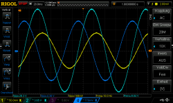
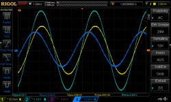
The rise in gain below around 2Hz is something that has been commented on earlier in thread and its a normal function of the opamp R/C time constants interacting with the amp input. If the source impedance is a few k then the issue is much less pronounced as shown here.

And with 3k source impedance:

And with 3k source impedance:
looks okay -its more then preamp-Lasse- suggested -
Your measurements agree pretty well with the simulation, that build is working fine!
No need to get hung up on those low-frequency measurements, as you should not encounter anything serious below 20Hz anyway. Otherwise you may have a look at the modifications that I did on my build, to take away some of the governance from the servo and tame that LF-peak.
The observed distortions are most probably caused by the PSU, like Mooly already suggested. Hook up a proper transformer and test again.
Thank you mooly.
Thank you Lasse.
Yes i remember about the peak and mods in some posts i read...
Thx
Chris
Thank you Lasse.
Yes i remember about the peak and mods in some posts i read...
Thx
Chris
Hi Mooly
thank you very much for your support.
the amp is up and running well.
yes its now a different sound with the correct value of the cap and the new 4,7µF wima as input cap.
THANK YOU
thank you Lasse for your support too
chris
thank you very much for your support.
the amp is up and running well.
yes its now a different sound with the correct value of the cap and the new 4,7µF wima as input cap.
THANK YOU
thank you Lasse for your support too
chris
Last edited:
@chermann - I've just been reviewing a lot of posts in this thread and noticed a possible problem with your build. The photo's in one of your posts a few pages back seem to show no chassis (safety) earthing ?, e.g., the second photo here: https://www.diyaudio.com/community/...signed-for-music.119151/page-100#post-7875372
I don't know the Austrian Regs., but I'm fairly sure in UK the mains safety Earth connection to the amp has to be taken directly to a permanent fixed chassis point, as soon as it enters the amp - might be worth checking.
I don't know the Austrian Regs., but I'm fairly sure in UK the mains safety Earth connection to the amp has to be taken directly to a permanent fixed chassis point, as soon as it enters the amp - might be worth checking.
- Home
- Amplifiers
- Solid State
- My MOSFET amplifier designed for music