left wrong...100 --> 10*10^0= 1nF
right correct cap

sorry guys...i am so sorry for that ...i feel shame..
chris
right correct cap
sorry guys...i am so sorry for that ...i feel shame..
chris

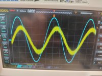
here are the measurements with the correct 0,1µF cap
please comment these.
thx
please comment these.
thx
Attachments

i am really happyPleased you found the error and that its all working now 🙂
....but the question is still in my mind...why does ist work a month ago?
I'm sure they will be fine. Its hard to decipher from pictures.
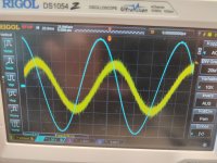
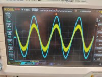
If you want to compare to the simulation then set the output for 4 volts peak (8 volt peak to peak) at 200 Hz. The output of the opamp should be around 15 millivolts peak (30 millivolts peak to peak).
It doesn't need a load for that.
If you want to compare to the simulation then set the output for 4 volts peak (8 volt peak to peak) at 200 Hz. The output of the opamp should be around 15 millivolts peak (30 millivolts peak to peak).
It doesn't need a load for that.
It might be worth checking the actual capacitors fitted in the three other locations on the board with the 0.1uF/250V component, especially the one in the Zobel network.
We've all been there!sorry guys...i am so sorry for that ...i feel shame..
Good troubleshooting to finally find the cause.
Because it does still work, just not very well. How bad it sounded would depend on the music content and how much bass there was.....but the question is still in my mind...why does ist work a month ago?
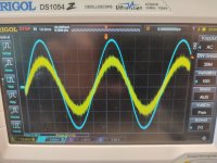
This is the response with 100pF. Look how the gain rises dramatically below 100Hz
without help not possible.We've all been there!
Good troubleshooting to finally find the cause.
Thank you mooly..!
and others.
checked!It might be worth checking the actual capacitors fitted in the three other locations on the board with the 0.1uF/250V component, especially the one in the Zobel network.
these caps or correct...
I'm sure they will be fine. Its hard to decipher from pictures.
If you want to compare to the simulation then set the output for 4 volts peak (8 volt peak to peak) at 200 Hz. The output of the opamp should be around 15 millivolts peak (30 millivolts peak to peak).
It doesn't need a load for that.
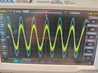
not okay.
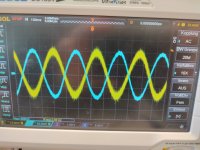
no load
yelow input
light blue ouput (no coil)
dark blue is the PIN 6 looks not okay.
it is more then 30mVpp
(the light in my "office" are horrible...)
Attachments

Because it does still work, just not very well. How bad it sounded would depend on the music content and how much bass there was.
This is the response with 100pF. Look how the gain rises dramatically below 100Hz
View attachment 1414337
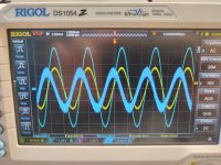
1nF....1000pF
It was last week so I'm guessing its still the same 😉 It is also 0.001uF1nF....1000pF
measured 1nF
That's strange, as it is clearly labelled 100pF. Do you have some similar capacitors handy to check your measurement setup?
Your scope plot looks fine to me. Maybe 50mVpp when you average out the noise and factor in some measurement and parts tolerances. Nothing to worry about, really.
Hi Lasse
i read that some manufactorer use 100 and that is a numbering code 1 0 0--->10^0=1nF...what ever
maybe a bad scope probe...its the cheap Rigol one here...
kr
chris
i read that some manufactorer use 100 and that is a numbering code 1 0 0--->10^0=1nF...what ever
maybe a bad scope probe...its the cheap Rigol one here...
kr
chris
- Home
- Amplifiers
- Solid State
- My MOSFET amplifier designed for music