
yes we have here a DC servo thats right.
but i am drive often my speakers (KEF R7) really loud with some hard bass attacks and i am not interested if a fail happened that my tweeters pop off the LS chassis.😉
but i am drive often my speakers (KEF R7) really loud with some hard bass attacks and i am not interested if a fail happened that my tweeters pop off the LS chassis.😉
Hi Chris,
My DC protection boards are powered from the main psu V+, but delayed ON/instant Off is controlled by a logic circuit built into the soft start module. I do not use extra AC/DC converters to power the DC protection boards. The MeanWell converter installed in the softstart module is used to power the local logic/housekeeping circuits.
My DC protection boards are powered from the main psu V+, but delayed ON/instant Off is controlled by a logic circuit built into the soft start module. I do not use extra AC/DC converters to power the DC protection boards. The MeanWell converter installed in the softstart module is used to power the local logic/housekeeping circuits.
Merry Christmas to all here!
i am happy with my amp with changing the bias (74mV) up to 168mA each line. so about 340mA. rail sag from original setup (47mV-about 110mA) from 41,3V to 40,61V rail.
i did this because i miss a bit of lower bass and get now a bit more "lovely", warmer sound.
for more bias i am afraid because T5, T3 get warm...poor boys 😉
kr
chris

Thank you Mr Mooly for this wonderful sounding amplifier….and thank you Mr Prasi for the excellent PCB’s!
I tried to blow it up last night but I failed…(my bad) thank goodness…very rugged design indeed.
Biased right up after correct drain to drain connection…..
Getting less than 2mv dc on output…takes a few to settle but no issues. Will experiment with output coil/resistor but without sounds really sweet.
Enjoy 2025, I will!
Attachments

hi
is there a LTspice file with double output MOSFEt?
i just found a lot with just one pair...
waht is the current at the last 2 lines /stages before ops?
T3/T5 is 6mA
T6/T7?
thx
chris
is there a LTspice file with double output MOSFEt?
i just found a lot with just one pair...
waht is the current at the last 2 lines /stages before ops?
T3/T5 is 6mA
T6/T7?
thx
chris
The standing current in T6/T7 can be calculated under no signal conditions by just taking the Gate/Source voltage when biased to the desired quiescent current. 100ma bias current sees around 0.4 volts between G and S and so I=V/R = 0.4/1500 or around 0.25 milliamps.
It doesn't matter how many pairs of FET's you have under no signal conditions as the gate current is essentially zero.
Under drive conditions things are more complicated because the driver current depends on the load impedance and how hard the FET has to conduct to achieve the desired output voltage into that load impedance.
Under no load conditions the driver current will vary only a little and so under say 8 ohm loading and at full output you might see a driver swing of 3 or 4 milliamps.
At high frequency the driver current increases a bit more because the gate capacitance of the FET also takes current to charge and discharge so the driver current is slightly higher at say 20kHz and full output into 8 ohms compared with 200Hz. Multiple pairs mean the capacitance increases further and that loads the driver just a little more but under all conditions the driver current is 'low'.
good morning
the reason why i am asking: (this year is not a good audio year -everything i touch is getting....)
a drive 2 weeks ago at the weekend to my brother with my amp in the car (it was cold) and as we want to start i guess that is ts okay to warm up the amp. inputs shorted during we listening the other amp. so i swiched on. no smoke normal warm up the heatsink nothing sepcial.
then we want to listen and compare.
the sound was horrible. no bass..crankly mids...we stopped. we found that the cheap RCA connector could be the problem because they move and are very loose?!..we changed but nothing changed with sound . we measured the rails and found nothing. nothing poped, smoked burned, smell....?
was it the difference between cold amp and a hart input current ivent?
that i was pissed was for sure.
i enjoy the M2ops thosiba with M2OPS mini
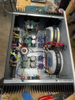
yesterday i start check in my lab:
both channels
rail okay
no smoke, nothing burned or smell strange
ops normal warm
TL071 voltage at pin 4 -11,9V, PIN 6 -4,98V both channels - perfect.
DC offset 0,32mV
because the amp is still mounted together i have to measure on different resistors.my lab supply can´t deliver more then 32V so i have to use the psu of the amp
CCS:
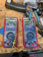
L channel measured at R5 - 577mV /100R --> 5,77mA -okay
R channel R12 -0,19V/3k9 --> 5,78mA -okay
VAS
L ch R17 0,79V/ 1k5--> 526µA --- i had noted during last perfect running amp -4,25V at R17 --> 2,8mA
R ch R22 0,927V/1k5 --> 618µA--- i had noted during last perfect running amp -3,97V at R22 --> 2,6mA
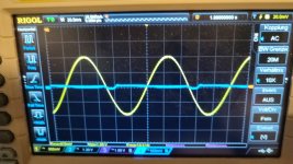
i checked with scope and there is some frequency dependency! - look at the pics
yellow is the input and if i change the frequency lower 1kHz my input signal of the FG will change?!
20 hz is visible and horrible
at 10hz the amp is diong nothing at the output -yellow input is clear
it looks like a frequency dependend behaviour with load the source hard at lower frequencies?!?!
over 2kHz the sine is perfect and this goes up to 130kHz without problems
at switched off -i checked with LCR my input caps. 10µF muse bip parallel 10µF muse ufg--> 100Hz up to 10kHz test frequency i got 18,8µF
ideas?
kr
chris
the reason why i am asking: (this year is not a good audio year -everything i touch is getting....)
a drive 2 weeks ago at the weekend to my brother with my amp in the car (it was cold) and as we want to start i guess that is ts okay to warm up the amp. inputs shorted during we listening the other amp. so i swiched on. no smoke normal warm up the heatsink nothing sepcial.
then we want to listen and compare.
the sound was horrible. no bass..crankly mids...we stopped. we found that the cheap RCA connector could be the problem because they move and are very loose?!..we changed but nothing changed with sound . we measured the rails and found nothing. nothing poped, smoked burned, smell....?
was it the difference between cold amp and a hart input current ivent?
that i was pissed was for sure.
i enjoy the M2ops thosiba with M2OPS mini
yesterday i start check in my lab:
both channels
rail okay
no smoke, nothing burned or smell strange
ops normal warm
TL071 voltage at pin 4 -11,9V, PIN 6 -4,98V both channels - perfect.
DC offset 0,32mV
because the amp is still mounted together i have to measure on different resistors.my lab supply can´t deliver more then 32V so i have to use the psu of the amp
CCS:
L channel measured at R5 - 577mV /100R --> 5,77mA -okay
R channel R12 -0,19V/3k9 --> 5,78mA -okay
VAS
L ch R17 0,79V/ 1k5--> 526µA --- i had noted during last perfect running amp -4,25V at R17 --> 2,8mA
R ch R22 0,927V/1k5 --> 618µA--- i had noted during last perfect running amp -3,97V at R22 --> 2,6mA
i checked with scope and there is some frequency dependency! - look at the pics
yellow is the input and if i change the frequency lower 1kHz my input signal of the FG will change?!
20 hz is visible and horrible
at 10hz the amp is diong nothing at the output -yellow input is clear
it looks like a frequency dependend behaviour with load the source hard at lower frequencies?!?!
over 2kHz the sine is perfect and this goes up to 130kHz without problems
at switched off -i checked with LCR my input caps. 10µF muse bip parallel 10µF muse ufg--> 100Hz up to 10kHz test frequency i got 18,8µF
ideas?
kr
chris
Attachments

oh...i forgot
in "cold" all ops lines show about 82mV at R23,R24 / R43,R44 final setup was 74mV --> 168mA
so OPS seams also okay
in "cold" all ops lines show about 82mV at R23,R24 / R43,R44 final setup was 74mV --> 168mA
so OPS seams also okay
Its difficult to figure out from your readings.
VAS current should be around 6ma.
Driver current is around 250uA with no signal.
The 1k5''s should have around 0.4 volts across them with no signal. The 4 volts you measure now would put the FET's into very hard conduction and they would be very hot and the bias current very high. This graph stops at 2 volts G/S voltage and is plotted at just 10 volts 'supply' across the device.

That possibly points to something amiss in the basic wiring and grounding. Given it was all working normally before (last month) and now there are problems after transporting it again points to something intermittent or something not insulated/isolated and touching something it shouldn't.
VAS current should be around 6ma.
Driver current is around 250uA with no signal.
VAS
L ch R17 0,79V/ 1k5--> 526µA --- i had noted during last perfect running amp -4,25V at R17 --> 2,8mA
R ch R22 0,927V/1k5 --> 618µA--- i had noted during last perfect running amp -3,97V at R22 --> 2,6mA
The 1k5''s should have around 0.4 volts across them with no signal. The 4 volts you measure now would put the FET's into very hard conduction and they would be very hot and the bias current very high. This graph stops at 2 volts G/S voltage and is plotted at just 10 volts 'supply' across the device.
it looks like a frequency dependend behaviour with load the source hard at lower frequencies?!?!
over 2kHz the sine is perfect and this goes up to 130kHz without problems
That possibly points to something amiss in the basic wiring and grounding. Given it was all working normally before (last month) and now there are problems after transporting it again points to something intermittent or something not insulated/isolated and touching something it shouldn't.
- Home
- Amplifiers
- Solid State
- My MOSFET amplifier designed for music