Good detective work 🙂
The gain difference is just the resistive divider effect of the 33k and 4k7 on the input signal. The opamp output although at around -6 volts is effectively 'ground' as far as signals go. If you add series resistance to the input voltage source it gives a similar effect of reducing that peak.
One interesting question is the effect when using with a passive volume control that has a variable source impedance. That does change the response at the extreme LF (way below where any audio is)
The 'servo' is really more than that as it provides the required DC bias voltage for the amp. If a fixed bias is applied say using a preset from a stable voltage source we get a more conventional response. Just run the sim and note the voltage at the opamp output and then substitute a voltage source of the same value via the same value 33k for biasing. DIsconnect the opamp and the output will be at 0 volts and the response will have no anomaly.
The 'servo' can then be added to close the loop and provide very light control via as here a 1meg.
In the real world such a bias scheme would be adjusted not by setting the DC offset of the amp to zero but by setting the opamp output to half its rail voltage ensuring it can swing equally either way. As long as the opamp output was not hard against a rail the main DC offset would always still be zero.

Hi
test yesterday evening failed 🤔 🙄
i have no psu to be safe and i do not expect strange things after successfully test with 31V.
rail psu okay...without amps connected 42V per rail...fine
SSR is not in operation
during test my 2A fuse blow off. i thought it was the inrush current of the 2x caps with 470µF.---that is nonsense
i do not realized this at the beginning so i go ahead ...i tried to measure the bias current and then is see that i have got nothing.
just changed the fuse to 4A fuse...what is a generally an stupid handling.
after short switch on i got got between the source resistors the nearly the full voltage!!!! - instead of 44mV
turn of poti is not reacting
i switch off i go pissed to bed...
i have to recheck my installation again
Last edited:
Sounds like you have some construction errors. Always use a DBT for initial testing, check the rails are correct with no load, then couple up the amp one channel at a time and see what's what.
Each channel should draw little more than 10ma per rail at zero bias, even with with the FET's in place.
Were your FET's genuine parts, not fake? such as remarked conventional power FET's which have a different pin configuration.
Each channel should draw little more than 10ma per rail at zero bias, even with with the FET's in place.
Were your FET's genuine parts, not fake? such as remarked conventional power FET's which have a different pin configuration.
Hi mooly
thx
i should use a 100R in the rails.
yes something must be wrong during build the amp...restart....
the rails are good and stable.
Renesas are genuine and no fakes. working well in my FX8 amps since 1 year without problems
thx
i should use a 100R in the rails.
yes something must be wrong during build the amp...restart....
the rails are good and stable.
Renesas are genuine and no fakes. working well in my FX8 amps since 1 year without problems
100 ohm should protect most things. If you short the bias setting resistor out, the amp still works normally but you force zero bias. If the resistors still burn you have an error somewhere.

Hi
Never a part was heating Up or burn.
Nothing.
All Channel are biased. Up and warm Up now.
SSR is installed
I did no mistake during building.
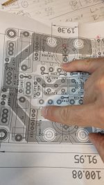
my stupid error was:
I do not use my near field glasses and i remember wrong about gate and drain of the upper and lower mosfet.
therefore i use my DMM (Set to mV) at the upper drain and the lower Gate!!!
Fuse blow 🙄 🤣🙄
The drain is per pair diagonal.
Now the amp is warming Up again...then i will check fg response....etc...
Thank you mooly for your Support.

Never a part was heating Up or burn.
Nothing.
All Channel are biased. Up and warm Up now.
SSR is installed
I did no mistake during building.
my stupid error was:
I do not use my near field glasses and i remember wrong about gate and drain of the upper and lower mosfet.
therefore i use my DMM (Set to mV) at the upper drain and the lower Gate!!!
Fuse blow 🙄 🤣🙄
The drain is per pair diagonal.
Now the amp is warming Up again...then i will check fg response....etc...
Thank you mooly for your Support.
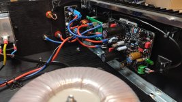
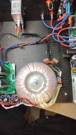
now it is burn in.
bias is about 46,6mV --> 101mA per MOSFET pair
Rail is about 41,3 Volt, PSU 300VA 2x30VAC, cap bank 4x 33mF.
burn in/test--> via a sine wave sweep of 100mVrms input 10Hz-50khz into 4R and about 4Watt.
heat sink of my 3U/300mm is just luke warm.
everything looks fine.... 😎
chris
bias is about 46,6mV --> 101mA per MOSFET pair
Rail is about 41,3 Volt, PSU 300VA 2x30VAC, cap bank 4x 33mF.
burn in/test--> via a sine wave sweep of 100mVrms input 10Hz-50khz into 4R and about 4Watt.
heat sink of my 3U/300mm is just luke warm.
everything looks fine.... 😎
chris
Hi
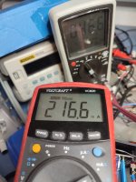
here are some short measurements.
gain is 32,5dB
8R -1kHz
max is about 490Vrms input
output is 62Vpp --> 57,2WATT
rail drop down to 37,5V
fg at 10Watt into 8R= 130kHz
4R
max is about 420Vrms input
output is 17,8Vrms --> 79WATT
rail drop down to 36V
for more power a bigger transformer is needed.
sound check is next step
kr
chris
Hi again
i do not compare to my other amps but this amp is a keeper.
the sound is clear, dark and at the higher end is clear and nice, not sharp and feels "open".
lower end is as i expected better than the FX8
sound stage deepness is very good...some titles come better from the back round...nice 🙂
plus enough power for home use and more.--->lucky i am under my terrace and have there a separate room 😎
thx mooly for that excellent amp.👍
Really pleased you are liking the sound of this one 🙂 Nice job you have done with the build.
Hi again.
i had a turn off pop and i think about my supply management. it was not a good idea to connect the SSR directly to the cap bank V+ because if the amps should deliver nearly full power (really loud) it comes to a short switch off off R channel or both channels.
i pick up the idea by Vunce (THANKS!) to install the AC/DC converter .
read here...
according to the datasheet this must be connected on the main power plug because you need more then 85VAC to get this work.
each AC/DC converter can deliver 1W...24V/42mA. one SSr need about 21mA. so it is better to use a seperate converter for each channel.

now it is perfect!
no turn off pop more!
kr
chris
i had a turn off pop and i think about my supply management. it was not a good idea to connect the SSR directly to the cap bank V+ because if the amps should deliver nearly full power (really loud) it comes to a short switch off off R channel or both channels.
i pick up the idea by Vunce (THANKS!) to install the AC/DC converter .
read here...
according to the datasheet this must be connected on the main power plug because you need more then 85VAC to get this work.
each AC/DC converter can deliver 1W...24V/42mA. one SSr need about 21mA. so it is better to use a seperate converter for each channel.
now it is perfect!
no turn off pop more!
kr
chris
Attachments
Last edited:
You really need a proper control circuit for either a solid state speaker relay (or a conventional relay), one that reliably gives the full delay at power on and that can dop out very quickly on power off.
These simple one transistor circuits are untested in the real world but should work reliably in practice.
Look how quickly the relay current falls when the AC is removed. AC voltage is derived from one side of the secondaries. A solid state relay can be substituted for the relay coil provided a suitable series resistor is used.
hi mooly
i am not sure why i should use your circuit because i have no on/off pop now.
my be i don't understand you idea.
kr
chris
i am not sure why i should use your circuit because i have no on/off pop now.
my be i don't understand you idea.
kr
chris
- Home
- Amplifiers
- Solid State
- My MOSFET amplifier designed for music