
good evening
i changed the value af R27 because of my lab supply just have 32V. so i use a 10k parallel to R27 =5k
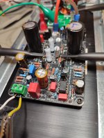
everything looks fine at the DC values. the L channel is out of the amp and still on the heatsink (3U 300mm)
same strange sine wave at lower frequencies without load!
 changing of opamp doesnt help .DC offset is nearly 0 / zero volt.
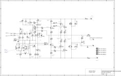
i did a schematic with al measured values.
Z-diode at the opamp shows 11,67Volt
kr
chris
i changed the value af R27 because of my lab supply just have 32V. so i use a 10k parallel to R27 =5k
everything looks fine at the DC values. the L channel is out of the amp and still on the heatsink (3U 300mm)
same strange sine wave at lower frequencies without load!
i did a schematic with al measured values.
Z-diode at the opamp shows 11,67Volt
kr
chris
The DC voltage conditions look fine (R17 and R22 currents calculated incorrectly 🙂)
Use the scope to check both - and + supplies are clean when the problem is happening. Make sure the grounds are configured correctly, again use the scope on the grounds to check they are clean.
Use the scope to check both - and + supplies are clean when the problem is happening. Make sure the grounds are configured correctly, again use the scope on the grounds to check they are clean.
Good morning mooly
yes..
oops ..... the current is wrong!
it si R22 618µA...R17 516µA
the amp makes the same failure -amp psu and lab psu.
i will check the rails and gan with scope...
thx
chris
yes..
oops ..... the current is wrong!
it si R22 618µA...R17 516µA
the amp makes the same failure -amp psu and lab psu.
i will check the rails and gan with scope...
thx
chris
yep...with 4 channel scope it have to be checked all.
+V, GND, -V and input signal
+V, GND, -V and input signal
Last edited:
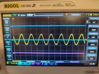
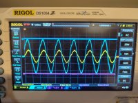
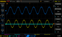
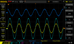
i did the scope measurements
ch1 yellow input signal is via T-connector to channel 1 and input via BNC-kroko
ch2 is signal output - or it is checking the GND
ch3 pink negativ rail
ch4 dark blue positive rail
i checked al situations the rails and the GND looks clean in every conditions. the signal is still distorted
ch1 yellow input signal is via T-connector to channel 1 and input via BNC-kroko
ch2 is signal output - or it is checking the GND
ch3 pink negativ rail
ch4 dark blue positive rail
i checked al situations the rails and the GND looks clean in every conditions. the signal is still distorted
Attachments
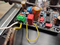
because the only frequency dependent component at the beginning is the input cap -in my situation 2x 10µF parallel i jumpered the caps.
hurra!! the signal is fine
strange that both caps 10µF muse and the UFG nichicon 10µF are defect.....but okay...get out!
hurra!! the signal is fine
strange that both caps 10µF muse and the UFG nichicon 10µF are defect.....but okay...get out!
Attachments
i changed to a WIMA 4µ7F and soldered this cap in....put i got the same situation. !!!!!!???? 🤔 😒 🙄 
input cap not okay...140Hz---if i jumper the cap then signal okay?!???
WHAT?
the PCB is clean and no wrong solder is possible and my solder joints are not bad after 40 years soldering.
maybe an imported information:
if i but out this yellow jumper cable the the singal is okay and all 2 seconds you can see that its getting more and more distorted.
kr
chris
Attachments

It won't be the opamp. Look at the output of the opamp and make sure it is just DC and no AC signal (apart from a very very small value that will rise as frequency falls).
More obscure reasons:
Make sure that if you are using an output coil (inductor) that it is air spaced and not one with a magnetic core.
Don't use and common mode chokes in the DC rails to the amp... I'm sure you are not but such things can do this.
More obscure reasons:
Make sure that if you are using an output coil (inductor) that it is air spaced and not one with a magnetic core.
Don't use and common mode chokes in the DC rails to the amp... I'm sure you are not but such things can do this.
Do you have a connection between input ground (AGND in your schematic) and power supply ground? Input ground is supposed to be connected via a separate wire to avoid ground current loops; it should not be connected on the PCB and thus may easily be overlooked and forgotten.
i measure without coil/before the coil. no my coil is an air coil.It won't be the opamp. Look at the output of the opamp and make sure it is just DC and no AC signal (apart from a very very small value that will rise as frequency falls).
More obscure reasons:
Make sure that if you are using an output coil (inductor) that it is air spaced and not one with a magnetic core.
Don't use and common mode chokes in the DC rails to the amp... I'm sure you are not but such things can do this.
but you are right
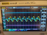
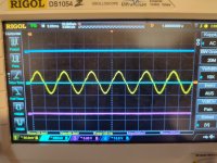
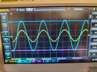
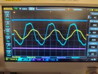
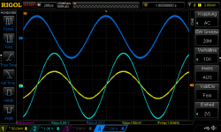
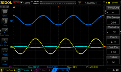
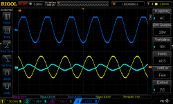
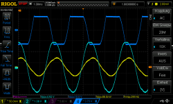
a have a lot of AC signal on the output pin 6 of the OPV
look at the pics - made 10minutes ago!
yellow input
light blue output (no coil)
dark blue PIN 6 OPV
kr
chris
Attachments
-
 1khz_yellow input lblue output dblue pin6 opv.png50.6 KB · Views: 32
 -
 10hz_yellow input lblue output dblue pin6 opv.png46.6 KB · Views: 36
 -
 10khz_yellow input lblue output dblue pin6 opv.png51.5 KB · Views: 33
 -
 50hz_yellow input lblue output dblue pin6 opv.png42.9 KB · Views: 27
 -
 90hz_yellow input lblue output dblue pin6 opv.png50.1 KB · Views: 30
 -
 300hz_yellow input lblue output dblue pin6 opv.png53.1 KB · Views: 30
- Home
- Amplifiers
- Solid State
- My MOSFET amplifier designed for music