Sebstian,
As Edcor has an agent in Germany, using 1 of their chokes instead of a Hammond part may be more cost effective. Edcor's XC87-2H-300 would be fine in your project's B+ PSU.
As Edcor has an agent in Germany, using 1 of their chokes instead of a Hammond part may be more cost effective. Edcor's XC87-2H-300 would be fine in your project's B+ PSU.
I have questions regarding the PSU:
Can I make the heater circuit to supply DC current?
also, How will I be able to pull out ~400V from the AnTec AS-3T325?
Tried making the PSU all by myself, but ended up getting headache
Can I make the heater circuit to supply DC current?
also, How will I be able to pull out ~400V from the AnTec AS-3T325?
Tried making the PSU all by myself, but ended up getting headache
I believe that Hungary is a "240" V. zone. Therefore, you wire the primaries in series. Put ferrite beads on the "free" primary wires. Toroids are wide bandwidth and you want to suppress garbage riding on the AC mains.
Phase up the 2X 325 V. secondaries and connect them in parallel. The "raw" B+ is obtained by bridge rectification. 4X 600 PIV Cree C3D02060F Schottkys are switching noise free. Pass the "raw" B+ through a CL-130 inrush current limiting thermistor and on to a CLC filter. Use 500 WVDC 105o C. 'lytics in the CLC filter. 220 μF. parts will be quite sufficient. A film part bypass of the reservoir (2nd) cap. is a nice touch.
A DC heater supply is a totally unnecessary frill in a power amp.
Phase up the 2X 325 V. secondaries and connect them in parallel. The "raw" B+ is obtained by bridge rectification. 4X 600 PIV Cree C3D02060F Schottkys are switching noise free.
Pass the "raw" B+ through a CL-130 inrush current limiting thermistor and on to a CLC filter. Use 500 WVDC 105o C. 'lytics in the CLC filter. 220 μF. parts will be quite sufficient. A film part bypass of the reservoir (2nd) cap. is a nice touch.A DC heater supply is a totally unnecessary frill in a power amp.
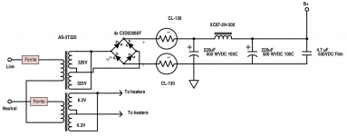
Only 1 CL-130 is needed. Put it on the "hot" side.
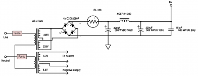
Do not connect the 6.3 VAC secondaries in parallel. One energizes the signal tube heaters. The 2nd 6.3 VAC winding will be used to feed the negative supplies voltage multiplier.
Make certain that you get the phasing correct, when windings are connected in series or parallel. The traditional way of indicating winding phasing in schematics is to put a dot at 1 end of the coil symbol.
Oh yeah, for this "Grande" use a 15 μF./630 WVDC metalized polypropylene part to bypass the B+ reservoir capacitor.
Last edited:
Okay, made everything what you said!
Wow, so many questions turned up:
What will be the 2 BIAS voltages to be used?
Is WVDC the same as VDC?
If I can't figure out the AS-3T325's phasing, since I can't find any wiring schematic on the internet. How can I find it out which are the phases without knowing?
Wow, so many questions turned up:
What will be the 2 BIAS voltages to be used?
Is WVDC the same as VDC?
If I can't figure out the AS-3T325's phasing, since I can't find any wiring schematic on the internet. How can I find it out which are the phases without knowing?
Attachments
Sure thing! Hammond supplies many Hungarian electronic shops!
Hi Obisix, I am also planning to build a tube amp, i am going to build a ST35 with some modification. However there is a polish company how made quite cheap transformers (main and output as well). Hammond is very expensive in Hungary....
Regards from Hungary
That schematic looks better.
One of the things caps. are rated for is the working voltage (WVDC). Sometimes, an explicit surge rating will be provided too.
Two negative voltages are needed: 1 for the CCSes (B-) and the 2nd for O/P tube bias (C-). A single voltage multiplier will be tapped in 2 places.
When you order the AS-3T325, make sure AnTek includes the color codes for the various paired windings. Each specific "top" and "bottom" type will have a unique color. Connect a "top" to a "bottom", for windings in series. Connect the 2 "tops" together and the 2 "bottoms" together, for windings in parallel.
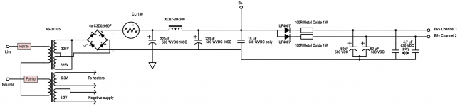
I'm not sure what Eli will suggest, but in the El Cheapo, the B2+ supply for the 12AT7 is formed by extending from the B+ take-off point, further filtering it to produce the slightly lower value for B2+.
By the way, Sebastian, I am a fan of the Hungarian bands ColorStar and Korai Öröm. Have you heard either?
By the way, Sebastian, I am a fan of the Hungarian bands ColorStar and Korai Öröm. Have you heard either?
So basically the B2+ Is actually the same as B+, but with additional filtering?
I do know them! I really love them, especially Korai Öröm!
Little is known about hungarian music, but we really do have some serious bands. There was a band 3-4 years ago in Hungary, called Tape Underground. Check them out if you love Trip Hop music! I'll post a link below
Tape Underground - Rég Volt
I do know them! I really love them, especially Korai Öröm!
Little is known about hungarian music, but we really do have some serious bands. There was a band 3-4 years ago in Hungary, called Tape Underground. Check them out if you love Trip Hop music!
I'll post a link below Tape Underground - Rég Volt
B2+ in this case will be slightly lower than B+, especially if you branch the left and right channels as in El Cheapo, adding a one-way diode and a small resistor and further capacitance. Earlier in the thread Eli specified the addition of 27K resistors in front of the 50K anode resistors for the 12AT7. This will knock down the final anode voltage on the 12AT7 a little more, since the B+ for your amp will be higher for the output tubes. The 12AT7 won't need as much.
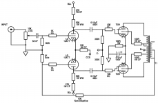
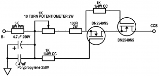
Use the schematic for the CCS that is in the El Cheapo schematic. It works well. I added a 15V Zener from source to gate in the "upper" MOSFET to solve a problem I had with static discharge killing that MOSFET in our dry winters.
The main differences with your amp from the El Cheapo will be voltage and current differences from the output tubes and whatever the best current in the 12AT7s will be to drive them. The El Cheapo works well at 3.5 mA in each section of the 12AT7s. I may have read earlier that Eli is suggesting 6 mA for this amp. I'm jumping in late, so I could be mistaken. If each CCS is operating at a total of 6-7 mA, the upper MOSFET will just get warm. If it's 6 mA per section and you're running 12 mA through each CCS, you may want to add a small heatsink to that MOSFET.
--Jeff
Yes, pin 1 and 6 are the plates (anodes). The CCS will connect through the single 10K heat isolation resistor and then to the cathodes, pins 3 and 8.
The voltage for the CCS is from the B- supply that Eli is working with you on. I think he wrote you that it will be derived along with C- (for the output tube grids) from the HT (high voltage) windings of the Antek transformer. It will be more than -15V, I think, where it enters the CCS at the bottom.
The voltage for the CCS is from the B- supply that Eli is working with you on. I think he wrote you that it will be derived along with C- (for the output tube grids) from the HT (high voltage) windings of the Antek transformer. It will be more than -15V, I think, where it enters the CCS at the bottom.
Okay, corrected the PSU, here it is, with B2+ outs also
Is this correct like this Eli?
I start to make the Half wave voltage multiplier schematic, I really want to finish the schematics today, since that's the only one left, if everything is good.
I also uploaded where I am now, every schematic, if you find aproblem, please tell me
Edit: Jeff, yeah, it will be delivered, but Eli, and I are planning on using voltage multiplier circuit from one of the 6.3V secondary to supply C- and B- this is why I am confused what voltages to get from the multiplier
Attachments
Last edited:
All,
7591 "El Cheapo Grande" or "12" W. O/P tube "El Cheapo", the needs of the 12AT7/ECC81 splitter driver must be accommodated. Repeat, the the 'T7 triode sounds good with 3.0 to 3.5 mA. of plate current and 200 to 220 V. on the plate. In a "Grande", the total plate load resistance is 77 Kohms. For an IB of 3 mA., 231 V. are dropped in the total load resistance. Therefore, B2+ needs to be in 431 to 451 V. range. 325 VRMS is 459.6 V. peak. However, the inevitable losses will bring the real world value of B+ down. We could get lucky and not have to change any parts' values associated with B+, but, until PSU "breadboarding" is done, don't count on it. If necessary, the carbon film part currently specified as 27 Kohms will have its value reduced.
I need to mull the negative voltages situation over. "Patience, Grasshopper."
FWIW, I whipped up an LTspice sim (just to approximate voltages), with a B+ of 450V. With 3.22mA per 12AT7 with the 50k + 27k plate load resistors, it showed 195V on the plates, 3V on the cathodes.
I've found that real life tubes often draw a little less current than their spice models, so it could be possible that you'd have to reduce the value of those 27k resistors in the end. But you wouldn't know until you built it and fired it up with the actual tubes you're going to use, right?
Remember that you can always put a 220k resistor in parallel with the 27k resistor if you need 24k in the end. Or put 120k in parallel with 27k if you need 22k, and so on.
(Those parallel resistors won't need to be expensive, high-wattage types, since they won't be seeing all the current going through the tube. I think 1/2 watt would do for those, while the 27k resistor would need to be rated 1W.)
--
Last edited:
- Home
- Amplifiers
- Tubes / Valves
- Choosing a tube amplifier to build, HELP needed