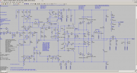
R28+C1 are the conventional location for the Output Zobel.
R84+C6 are the alternative location for the Output Zobel, proposed by N.Thiele.
L1||R49 plus either of the Zobels is the Thiele Network.
Using both the Zobels and the Inductor is the Pi version of the Thiele Network.
When analysing the stability, one usually taps in before the Inductor to measure the amplifier output.
This is also where parasitic capacitance is added to test the model for adequate phase margin.
If one wanted to analyse the effective isolation provided by the Thiele Network one would tap in after the inductor.
If one is analysing the amp's stability margins, then Cload should be tapped in before the inductor.
Cload as shown, is isolated from the amplifier feedback node and has very little effect on stability margins if the Thiele Network is effective.
Last edited:

So what Cload on the left side of the inductor should be inserted for testing?
Which Cload has to be accepted so we can say the amplifier is stable?
Is there a rule of thumb?
THX in advance, Toni
Last edited:
I have seen suggestions of trying over the range 1nF to 1000nF.
But you may have to increase the Rload to around a value similar to the peak impedance value of typical speakers. Some go as high as 100r resistive, where the phase passes through zero degrees (the horizontal portion at the tops and bottoms of the impedance curve).
So it could that trying a combination of Cload and Rload both stepping through a range of values to see that a weird combination does not make the amp oscillate.
Are there any out there that disagree that Ctest (Cload) should be placed at the amp output?
You have all gone very silent !
You have all gone very silent !
Are there any out there...
Me, more or less.
The capacitance is intended to simulate the effect of speaker cable capacitance and speaker stray capacitance, especially from transformers in electrostatic models.
These all attach after the output inductor, it's precisely the point of the inductor, to isolate these loads.
So that's the traditional test.
But it doesn't seem like a bad idea to check the sensitivity of the amp to stray layout capacitance as well. Hence before the inductor.
But realistic values at this point will tens or maybe a few hundred pF.
Best wishes
David
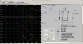
Cload placed on left side of output L||R network. R_LOAD was 8R.
At least stable up to 18nF (PM > 35dB, GM > 6dB).
Without R_LOAD and L||R network circuit delivers near same stability.
Left 4.7R/100nF Zobel is always needed to keep the amp stable.
Inner loop seems to be always stable?
L||R is always needed if the load is a speaker with parallel capacity up to 2µ.
Thx David! It really makes sense to check both sides of Zobel/Thiele network.
BR, Toni
Attachments
Last edited:
I am failing to completely stabilise three different Symasym builds (on three different Members' PCBs).
Adding just 4.7nF of output to ground capacitance can throw the amp/s into full oscillation.
Zobel was placed? L||R network available? before or after inductor?
BR, Toni
...Thx David! It really makes sense to check both sides of Zobel/Thiele network.
Thanks to Andrew really, it was his question that made me think about it at all.
Best wishes
David
Thanks to Andrew really, it was his question that made me think about it at all.
Best wishes
David
Hi! Of course thanks AndrewT too!
BR, Toni
No inductor yet.Zobel was placed? L||R network available? before or after inductor?
BR, Toni
I am testing the amplifiers.
I do include the inductor in all my builds.
I have recently (maybe 2 years or so) used the Pi version for all new builds, since I cannot find any fault in doing so.
I do believe that attenuating interference at all the cable entries is a valuable method of giving the amplifier a good chance of behaving as designed/intended.
Last edited:
...
But it doesn't seem like a bad idea to check the sensitivity of the amp to stray layout capacitance as well. Hence before the inductor.
But realistic values at this point will tens or maybe a few hundred pF.
...
For the 200W brother I've measured about 800pF stray capacitance from output to heatsink (grounded) using 8 pairs of TTC5200/TTA1943 so for simulation I think it is really necessary to add some hundred pF Cload before Zobel/Thiele network. What do you mean?
BR, Toni
On that basis, my finding that 4n7F (4700pF) attached before the inductor and causing a testing problem, should not be a concern.
But I am concerned, so much so, that each of the variants has been placed aside to see if any others were as bad, or any better/worse.
But I am concerned, so much so, that each of the variants has been placed aside to see if any others were as bad, or any better/worse.
For the 200W brother I've measured about 800pF stray capacitance from output to heatsink (grounded) using 8 pairs of TTC5200/TTA1943 so for simulation I think it is really necessary to add some hundred pF Cload before Zobel/Thiele network. What do you mean?
That is a bit more than I expected, by "a few hundred" I meant maybe 300 pF.
8 pairs is more than most amplifiers, so that accounts for some of it.
I did some capacitance calculations for transistors on heat-sinks with thermal washers but I don't remember it was so much.
Could be my memory or perhaps my assumptions, how are your transistors mounted?
Best wishes
David
Many very experienced Members here suggest 100nF as a test Cload. Many of these only use an output Zobel and no inductor.
They seem to be at odds with what is now being discussed.
They seem to be at odds with what is now being discussed.
Many very experienced Members here...use an output Zobel and no inductor...
Who?
Of the experienced members whose posts I pay attention to, I have not noticed any omit the inductor in a practical amp.
Ric Lee is _very_ experienced and considers it practically essential.
Bob Cordell of course.
Toni here uses it.
Damir (Dadod) and Andrew (Bonsai) also IIRC (my files are on another machine so I can't easily check).
OStripper in the amps of his that I have noticed (he's done a lot so I wouldn't swear to all).
Those are just the ones where I remembered an output inductor in a finished amp, sorry if I have omitted anyone, doesn't mean I don't pay attention to you.
Best wishes
David
I know John Curl discusses this and I know he is experienced but he seems to prefer controversy so he is not one "whose posts I pay attention to".
Last edited:
...
Could be my memory or perhaps my assumptions, how are your transistors mounted?
...
Using Keratherm type 86/82 red, Datasheet: http://www.kerafol.com/fileadmin/us...gement/produkte/86_82/Datenblatt_86_82_EN.pdf
Available at e.g. Conrad Electronics
Many very experienced Members here suggest 100nF as a test Cload. Many of these only use an output Zobel and no inductor.
...
IMHO omitting the inductor doesn't allow to connect speakers with high capacitance.
And 1m of speaker cable can easily have hundred pF. So adding extra 1nF Cload would be a good Idea too.
Using Keratherm type 86/82 red, Datasheet: http://www.kerafol.com/fileadmin/us...gement/produkte/86_82/Datenblatt_86_82_EN.pdf
Fine, Keratherm is one of the best products I have been able to find and I plan to use it too.
Just wanted to check you didn't have a copper bus bar or some other non standard structure that didn't fit my assumptions.
How did you measure the capacitance?
Best wishes
David
...
How did you measure the capacitance?
...
with all cables removed but pcb/bjt's mounted on heatsink.
Peaktech 2165 USB connected to heatsink and output at emitter resistors.
- Home
- Amplifiers
- Solid State
- 2stageEF high performance class AB power amp / 200W8R / 400W4R