have fun 😛😀🙂
Attachments
-
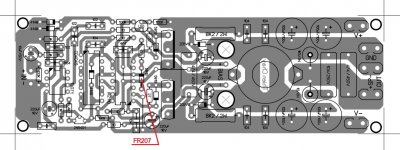
irs 900d corect artwork print .pdf351.5 KB · Views: 1,682
-
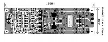
IRS-900D _ PCB 2 thienchay spaced small artwork.pdf342.2 KB · Views: 1,532
-
 irs500 component.jpg132.5 KB · Views: 3,815
 -
 ab722e449ca921e4.jpg250.2 KB · Views: 3,728
 -
IRS-900D _ Overlay_ checked.pdf104.2 KB · Views: 1,280
-
 IRS-900D _ Overlay_ checked.jpg166 KB · Views: 3,650
Hello diyrs ask if were can i buy irfp4668 and irfb4227?
RS Components | Electronic and Electrical Components
Farnell element14 UK - Electronic Components Distributor
Conrad-Electronic.co.uk - Think technology, think Conrad UK, home to over 155,000 products
I have experienced some weird things with this design. Week ago i put this thing together from junk parts and it worked perfectly. Very clean switching waveforms, i was surprised. Only thing heating up was the random iron powder toroid at the output filter which was obviously bad material for this application. Since this amplifier is driving 4ohm subwoofer i came up with 32µH inductor and 2µF capacitor.An externally hosted image should be here but it was not working when we last tested it.
Later on i replaced the overheating toroid with impedance matching choke from my induction heater project which is good up to 125Amps at 40kHz. Big surprise was that when the choke was set to exactly same inductance than the smoking hot one, the amplifier lost its stability.
Problem i noticed is switching frequency and duty cycle are jumping all over the place, and voltage in positive rail is creeping up like 1V/second which means i have DC offset at the speaker output. Now the weird thing is, when i unplug the signal source (mobile phone or laptop, both isolated) the positive rail creeping and instability go away.
No matter what, i could not get the 32µH inductor to work on ferrite core, but it works perfectly on super lossy iron powder. Interestingly though, if i remove the air gap completely, total inductance is around 110µH and the amplifier once again works perfectly, but output impedance is of course nowhere near i want it to be, and the positive rail voltage creepage is still there. In this condition i measured whopping 824W DC input power when i rattled whole building with 15" subwoofer and nothing got hot or exploded 😀
yep . i think that is what i was trying to point out in my previous posts about sigma delta amp.
http://www.diyaudio.com/forums/clas...00-watts-using-2-mosfets-364.html#post3600975
http://www.diyaudio.com/forums/clas...00-watts-using-2-mosfets-366.html#post3611890
http://www.diyaudio.com/forums/clas...00-watts-using-2-mosfets-365.html#post3608139
http://www.diyaudio.com/forums/clas...00-watts-using-2-mosfets-364.html#post3600975
http://www.diyaudio.com/forums/clas...00-watts-using-2-mosfets-366.html#post3611890
http://www.diyaudio.com/forums/clas...00-watts-using-2-mosfets-365.html#post3608139
Hi stewin,
without DC protect all IRS900 & AUD600 etc.. will fail during start up
Regards
MANOJ
without DC protect all IRS900 & AUD600 etc.. will fail during start up
Regards
MANOJ
Hello from Ukraine.
I want to collect the amplifier for the subwoofer.
Stopped on the amplifier IRS-D900. I noticed that there are two types of fees. In post # 3941 are shown both. What is proven and can collect it. What is working?
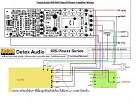
Detex Audio IRS-900D V 2.0 or Thien Chay pcb???
If you have these cards in the format .lay would be very grateful for your help.
I would be grateful to all who will respond and help thanks in advance.
P.S.
Sorry for my english.
I want to collect the amplifier for the subwoofer.
Stopped on the amplifier IRS-D900. I noticed that there are two types of fees. In post # 3941 are shown both. What is proven and can collect it. What is working?
Detex Audio IRS-900D V 2.0 or Thien Chay pcb???
If you have these cards in the format .lay would be very grateful for your help.
I would be grateful to all who will respond and help thanks in advance.
P.S.
Sorry for my english.
thanks manoj for the reply i will impliment protect. hi andrew which topology is your bridge amp sigma or ucd? how many volts?? can it support 2ohms in bridge mode?
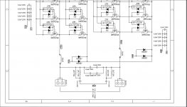
that is my schematic.
It works very well but you've to tune the circuit with real components.
I prefer the IRS20957 version because there are less components, more protection and best performance.
Hey pergo,
I ran a LTSpice simulation of the schematics attached which I believe it's yours.
There are 93A current spikes through the final MOSFETS due to simultaneous conduction.
How would you tune the schematics to remove the spikes ?
Attachments
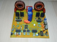
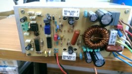
hier is my irs 3000 modified sound is very hight quality
Attachments
Last edited:
hier is my irs 3000 modified sound is very hight quality
hi
can you share you pcb and info about your irs 3000?
Hello,
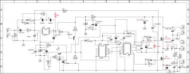
..when I saw this modified schematic done by Joel of DIYsmps, it got me interested to resurrect IRS900D 🙂 and after my initial test of Manoj mod on ApexD200, I made some changes (in red color) from the original design of Detex and also with Joeys' mod. I'd like to use the mid-power TO-220 devices for the output because they are easily available and cheaper too.
Here is the schematic and the pcb design...any thoughts before I construct this amp?
Attachments

Last edited:

Hi Razamir,
Use T 106-2 micormetals iron powder core for the output inductor.
Regards,
Savu Silviu
dear razamir
would you like to share pcb and details.i would highly oblized
thanking you
- Home
- Amplifiers
- Class D
- UCD 25 watts to 1200 watts using 2 mosfets