my irs:
https://yadi.sk/i/2F1PSP1YeGuNW
https://yadi.sk/i/wBu1I2rseGuGa
https://yadi.sk/i/Ug2XaHIHeGuBu
An externally hosted image should be here but it was not working when we last tested it.
https://yadi.sk/i/2F1PSP1YeGuNW
https://yadi.sk/i/wBu1I2rseGuGa
https://yadi.sk/i/Ug2XaHIHeGuBu

Wow dude, where is your protective ground? Looks risky to me.
Wow dude, where is your protective ground? Looks risky to me.
amplifier circuits + preamp circuit +secondery side of SMPS + aluminium plate
are fully touchable,no electroshoks
Its looks like risky but no risk @ normal operation
worst cases sometims protective ground become serious
I dont have idea about it.
I dont have idea about it.
Better make sure that nobody comes close to your installations, especially not your small child.
😉
😉
Better make sure that nobody comes close to your installations, especially not your small child.
😉
I have a problem with my irs900d beacuse I have an output of 1V DC (MOSFETs have different opening times)..how to deal with it?
How can I adjust the dead time?
How can I adjust the dead time?
I have a problem with my irs900d beacuse I have an output of 1V DC (MOSFETs have different opening times)..how to deal with it?
How can I adjust the dead time?
IRS900d don't need dead time adjestment manuely,its optimised
check pin 10,12 of IR2110
http://www.diyaudio.com/forums/class-d/166214-ucd-25-watts-1200-watts-using-2-mosfets-253.html
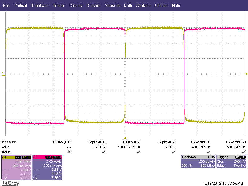
blue pin 12, yellow pin 10
An externally hosted image should be here but it was not working when we last tested it.
An externally hosted image should be here but it was not working when we last tested it.
Last edited:
An externally hosted image should be here but it was not working when we last tested it.
first you have to change CD4049 logicinveter ic
An externally hosted image should be here but it was not working when we last tested it.
sorry, blue is pin 10 on cd 4049, yellow is pin 12An externally hosted image should be here but it was not working when we last tested it.
I started a new cd4049 and this is the same as it was.
An externally hosted image should be here but it was not working when we last tested it.
The output dc has decreased to the normal level
Last edited:

this solve the problem
but it add some dead time and unbalence @high volume
extra heat on cd4049
Dinithm the problem is still...🙁
yellow pin 10 Ir2110, blue pin 12

Negation gate propagation delay is too long? 100ns difference
Output without the input signal, DC 0,8V.
yellow pin 10 Ir2110, blue pin 12
Negation gate propagation delay is too long? 100ns difference
Output without the input signal, DC 0,8V.
An externally hosted image should be here but it was not working when we last tested it.
Last edited:
you can add some extra dead time using this,
befor check output snubber(soble network)
and IR2110 IC
An externally hosted image should be here but it was not working when we last tested it.
befor check output snubber(soble network)
and IR2110 IC
D
Deleted member 148505
hello i read through the thread and find that a lot of of talking about noise.i have noise too.and i succefully get rid of it by filtering the inputs.
i think the noise comes from unstablility nature of the frequency of this type of self osc amp.
the frequency of this amp determined by the phase delay of the active device,LC filter,and phase lead of feedback network.in which the delay of active network plays an important role.a little change of active delay can generate big frequency shift.this is because the slope of phase-freq curve is flat near 180 degree in the bode plot.you can read inventer's paper to see this.
it is interesting that when i debug this amp i find its osc freq will lock to the input audio signal,just like a PLL's behave.for example if i inject 20khz then the osc freq will be exactly 20*16=320khz while free osc at some place near 320khz.this is the evidence of its unstable frequency.
the change of osc frequency cause a lot of high band noise mirror into audio frequency.so the noise sounds something like mirror interferrence in the am radio.
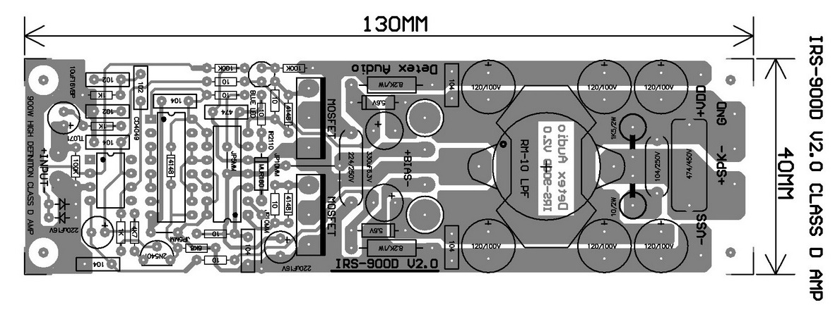
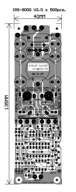
IR9OO
LAYOUT-PDF😎
what r differences between these?!
Attachments
hello, personal diy audio I wonder if I can pass the pdf files for tailoring irs900d for thermal transfer ... grateful !!!!
ir900
hello, friend !!! can pass me the pdf files to transfer the ir900 ?? grateful !!^ OK! thanks,
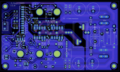
My etched pcb for IRS900D (done manually😀), thanks Thien!
An externally hosted image should be here but it was not working when we last tested it.
An externally hosted image should be here but it was not working when we last tested it.
(Sorry, been using cellphone cam 🙂)
- Home
- Amplifiers
- Class D
- UCD 25 watts to 1200 watts using 2 mosfets